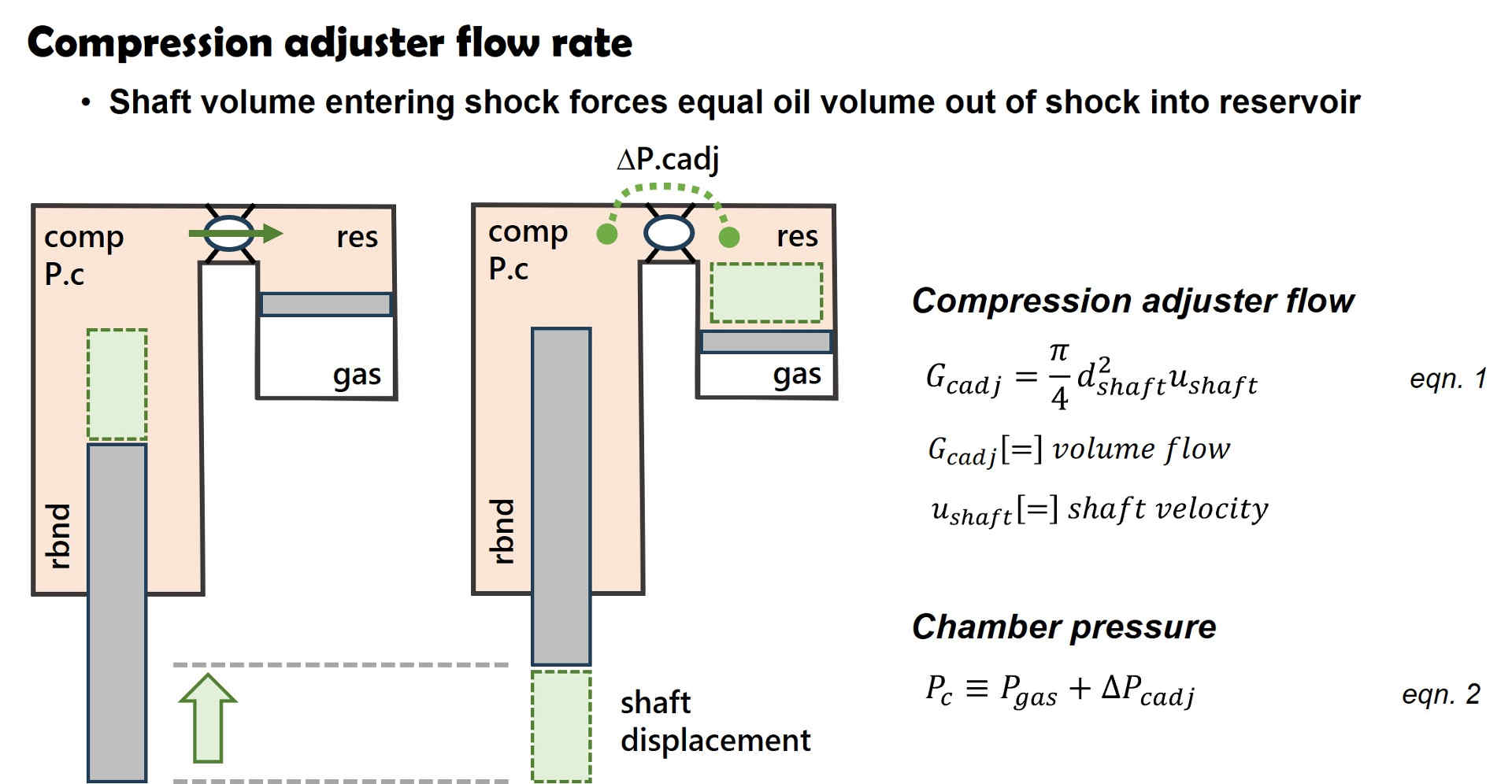
The oil flow rate through the compression adjuster, or base valve on a fork, is driven by the shock shaft volume entering the shock. The shock shaft volume displaces an equal volume of oil out of the shock through the compression adjuster into the oil reservoir.
The Ohlins MX4 shim stack below is an example of a faux crossover. The pair of shims forming the crossover can be repositioned into the stack taper forming a simple tapered shim stack with the same damping force confirming the crossover gap is faux.
Based on an incompressible fluid, the volume flow rate through the base valve is equal to the shock shaft area multiplied by the shaft velocity. Thus, the oil flow rate through the compression adjuster is set by the shock shaft diameter and shaft velocity, (eqn. 1).
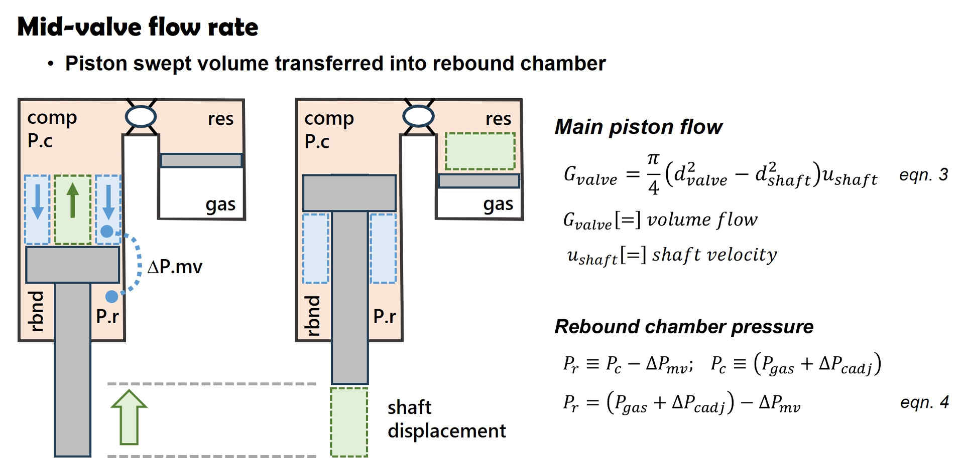
Mid-valve flow rate
The mid-valve piston sweep area is equal to the piston face area minus the shaft area. The oil volume swept by the mid-valve is forced through the piston into the rebound chamber. The piston sweep area multiplied by the shaft velocity defines the volume flow rate through the mid-valve (eqn. 3).
Chamber pressure
The fluid pressure in the shock compression chamber (P.c) is set by the reservoir gas pressure plus the pressure drop across the compression adjuster (eqn. 2). The rebound chamber pressure is set by the compression chamber pressure minus the pressure drop across the main piston, (eqn. 4).
Shock absorber circuit flow rate
Equations 1 through 4 define the oil flow rate through shock absorber circuits. The circuit flow rate is independent of pressure drop as long as the circuits are not cavitating. The equations also define the pressure in each shock chamber. The oil will cavitate when the chamber pressure drops below the oil dissolved gas pressure which allows the dissolved gas to boil out and foam the oil.
Oil compressibility
A pressure increase of 1,000 psi compresses hydraulic oil by 0.5% (engineers edge), approximately equivalent to the compressibility of water.
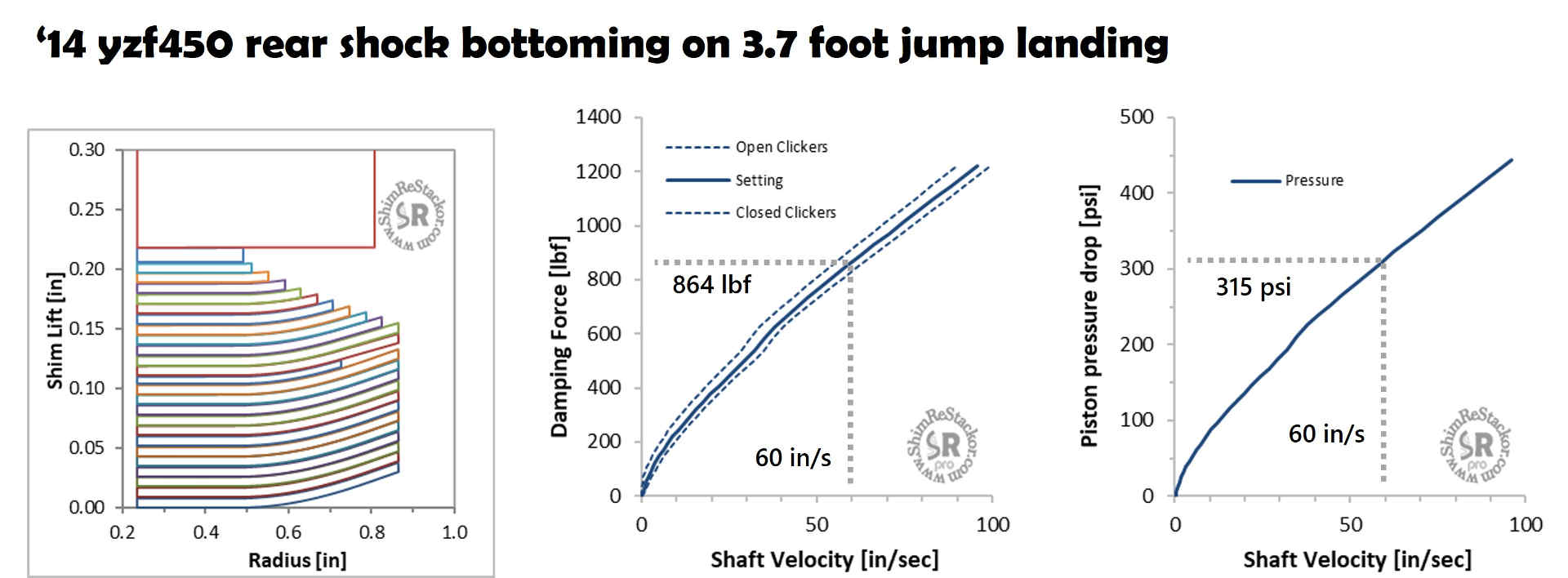
Shim ReStackor suspension response calculations show a 3.7 foot freefall will bottom a ’14 yzf450 rear shock with an impact velocity of 186 in/sec (linky). The impact results in a shock peak pressure of 315 psi.
Given an oil compressibility of 0.5% at 1,000 psi the 315 psi shock pressure produces a 0.5*(315/1000)= 0.16% increase in oil density. On a five inch shock stroke the compressibility allows the shock shaft to jump forward 0.008 inches in a phenomena know as compressibility surge.
The shock absorber damping force scales directly with oil density. So, a 0.16% increase in oil density produces a 1.4 lbf increase in damping force.
The bump energy absorbed by a shock is equal to the force times distance work done. The oil density compressibility increase results in a 0.16% increase in damping force while the compressibility volume reduction decreases the shock stroke by 0.16%. The 0.16% increase in damping force is offset by the 0.16% decrease in stroke length resulting in no net change in the force times distance energy absorbed by the shock.
Oil compressibility of 0.5% at 1,000 psi is very small and produces an inconsequential change in shock absorber performance confirming the commonly reported result “Shock absorber oil is virtually incompressible”.
Flow through opposing valves
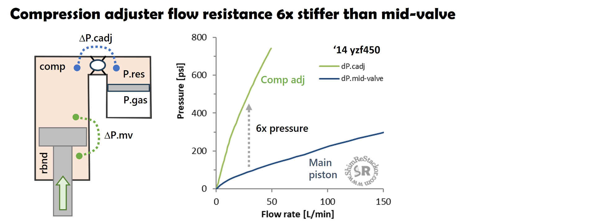
Flow through the opposing valves of a shock absorber is frequently referred to as a complex fluid dynamic problem creating uncertainty in the exact flow splits between the circuits due to the parallel paths. While mentally confusing for some, the shock absorber oil is not confused. Fluids take the path of least resistance. For a yzf450 shock shown below the path of least resistance is through the main piston.
Oil flow through the compression adjuster is forced by the shock shaft volume entering the shock which pushes an equal volume of oil through the six times stiffer flow resistance of the compression adjuster.
The high compression adjuster flow resistance forces high pressures in the shock compression chamber which help to suppress oil cavitation and foaming in the shock.
Thus, the two circuits operate simultaneously and independently. The piston sweep area sets the flow rate through the main piston while shaft volume displacement sets the flow through the compression adjuster. These separately tunable circuits provide a very important function allowing pressure balancing of the shock chamber pressures to suppress cavitation and oil foaming in the shock absorber chambers (linky).