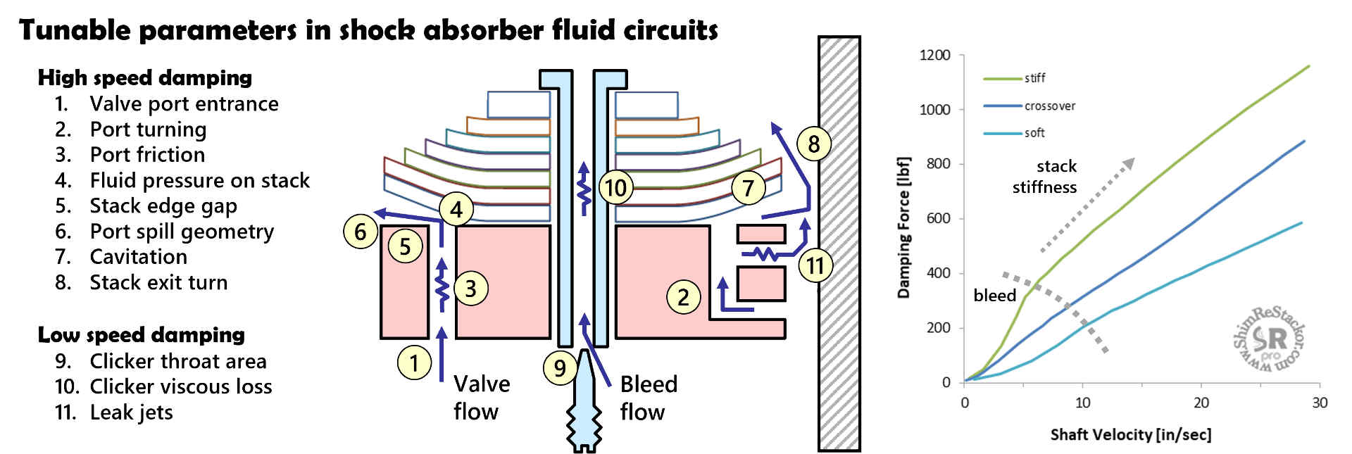
Shim ReStackor models eleven tunable features of shock absorber circuits. Bleed systems control low speed damping. Flow restrictions control high speed damping, bottoming resistance and suspension deflection off sharp bumps.
Tuning low speed leak jets and high speed flow restrictions gives additional control of the shape of the damping force curve beyond the fundamentals of shim stack tuning.
Clicker bleed circuit
Shim ReStackor models seven factors controlling flow resistance through clicker bleed circuits. The discussion below steps through the clicker circuit with flow in the rebound direction.
Flow losses in the reverse compression stroke are slightly different due to the flow approaching each geometry feature in the opposite direction.
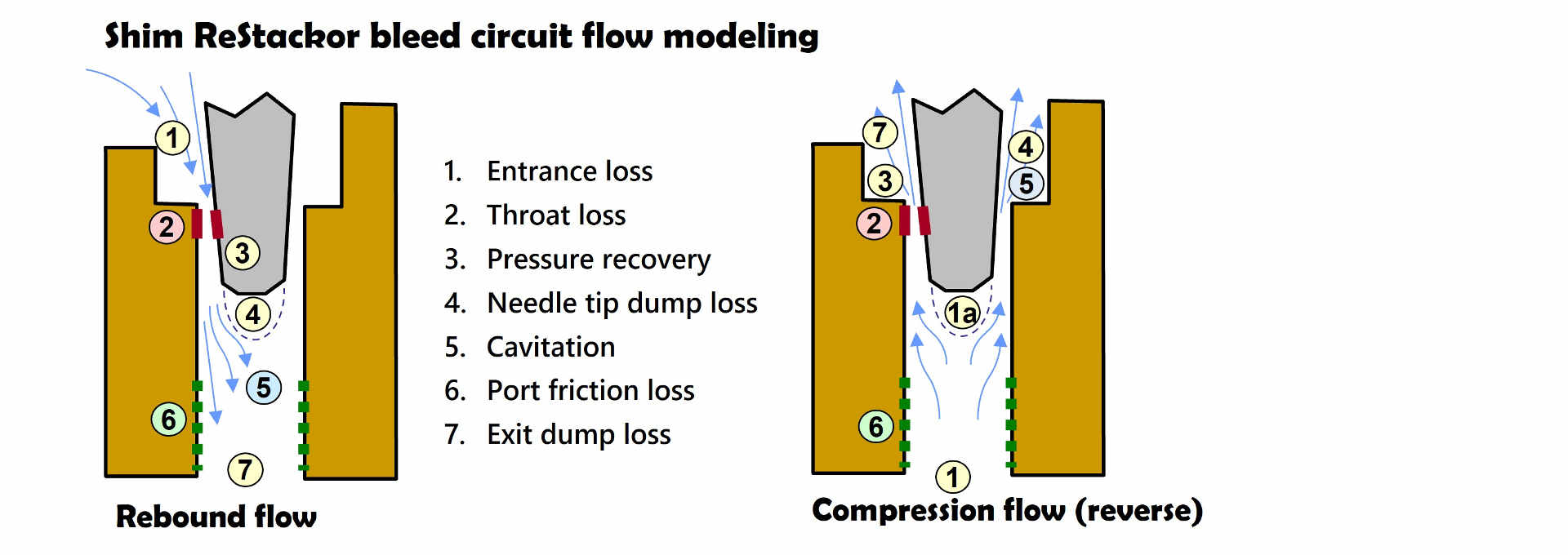
1. Entrance loss
Velocity gradients between converging streamlines in the port entrance create viscous shear losses due to the velocity differences in each streamline. Higher oil viscosity increases the entrance loss.
2. Throat loss
The highest flow velocity occurs at the clicker throat. The throat minimum area is defined by the needle taper and clicker position. The relationships used in ReStackor to define the minimum throat area have also been adopted for use in other shock absorber performance studies. (P. Skackauskas, Maintenance and Reliability 19(1):126-133, 2017).
The clicker throat flow resistance is a combination of pressure forces required to accelerate the fluid through the minimum area and skin friction viscous losses through the high velocity throat region. At the near closed clicker position the ratio of surface area to flow area is extremely large making viscous losses the dominate pressure loss.
3. Pressure recovery
Downstream of the throat, the expanding flow created by the needle taper decelerates the flow. Pressure recovery through the deceleration region depends on the peak velocity, boundary layer thickness, viscous friction loss and the needle taper angle. Each parameter is modeled in Shim ReStackor bleed flow calculations. Stiff shim stacks force higher flow rates though the clicker circuits and the higher velocities force flow separation from the needle surface resulting in higher clicker circuit flow losses with stiffer shim stacks.
4. Needle tip dump
At the needle tip the flow separates from the needle surface creating a dump loss. The magnitude of the pressure loss depends on the flow velocity at the needle tip, which in turn depends on the effectiveness of the needle tapered section in decelerating the throat velocity as the flow approaches the needle tip.
5. Cavitation
Cavitation creates the psst, psst sound frequently heard rolling over small bumps. Stiff shim stacks, high bleed circuit flow velocities and large flow expansions at blunt needle tips cause bleed circuit cavitation noise. Once cavitated, the cavitation separation bubble crawls up the needle taper to the point where bleed circuit flow losses balance with the dissolved gas vapor pressure in the oil. Shim ReStackor fluid dynamic calculations include cavitation effects and the effect of oil temperature on dissolved gas vapor pressure.
6. Port friction loss
Downstream of the needle tip the flow expands to the bleed port area. The expansion decelerates the flow which reduces viscous friction losses through the remainder of the bleed circuit. ReStackor uses Reynolds number based skin friction relationships to determine the viscous flow losses and the transition from laminar to turbulent flow.
7. Exit dump
At the bleed port exit the flow spills into the downstream fluid reservoir. The sudden expansion produces an additional dump loss evaluated using the same procedures as the needle tip dump loss.
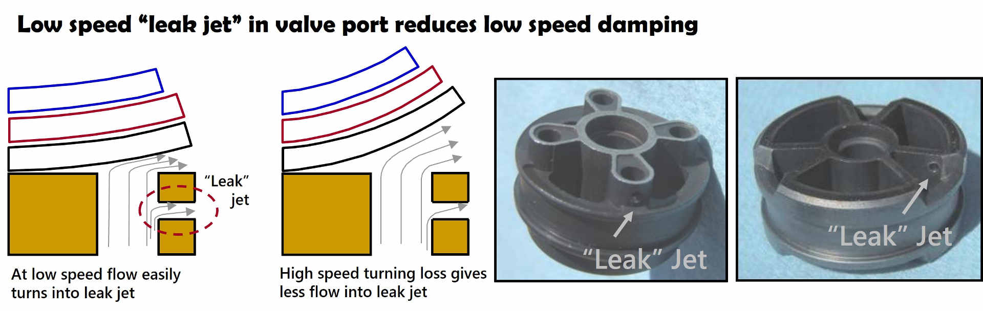
Valve port leak jet
Leak jets are small holes drilled in the side of the valve port. At low speed, pressurized fluid escapes through the leak jet which reduces the damping force.
At high speed, flow velocities in the valve port are unable to negotiate the sharp 90 degree turn into the leak jet resulting in reduced flow through the leak jet and a reduced effect on damping force. (linky sample apps).
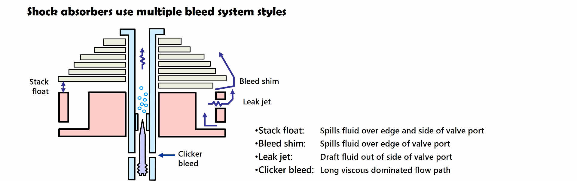
Bleed system effectiveness
Notionally, 1 mm2 of bleed flow area through a leak jet, bleed shim, stack float or clicker bleed circuit produces the same effect on damping force. However, the long flow path of a clicker bleed circuit increases viscous flow losses and reduces the effectiveness of clicker bleed. Bleed shims or stack float directly vent flow out of the valve port resulting in small viscous losses and increases the bleed effectiveness while the 90 degree turn into a leak jet port reduces the bleed effectiveness at high speed. (linky sec3.2.7).
Shim ReStackor calculations account for the differences in flow resistance between different styles of bleed circuits. Tuning bleed systems to achieve a specific damping force is a simple matter of increasing or decreasing the bleed circuit flow area or adding additional leak jets on the valve ports until the desired damping force value is achieved.
Shim ReStackor handles the detailed fluid dynamic calculations so you can focus on tuning the shock to produce the desired damping force.
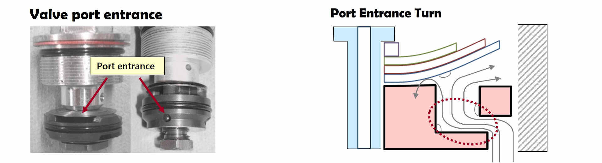
Port entrance loss
Fluid enters the main piston valve port through an annular slot formed between the valve deck and reverse flow shim stack or through holes drilled in the side of the valve body. In either case flow area is the critical parameter controlling flow losses.
Valve port entrance losses can be minimized by increasing the port area or adding delta shims to the reverse flow shim stack to raise the shim stack above the valve deck to increase the port entrance flow area.
Port entrance turn
Downstream of the port entrance the flow turns 90 degrees generating a flow loss. Shim ReStackor models the flow loss as a sharp 90 degree turn using a flow loss model developed through dyno testing.
Increasing the entrance port area reduces the flow velocity and the resulting port turning loss inside the valve port.
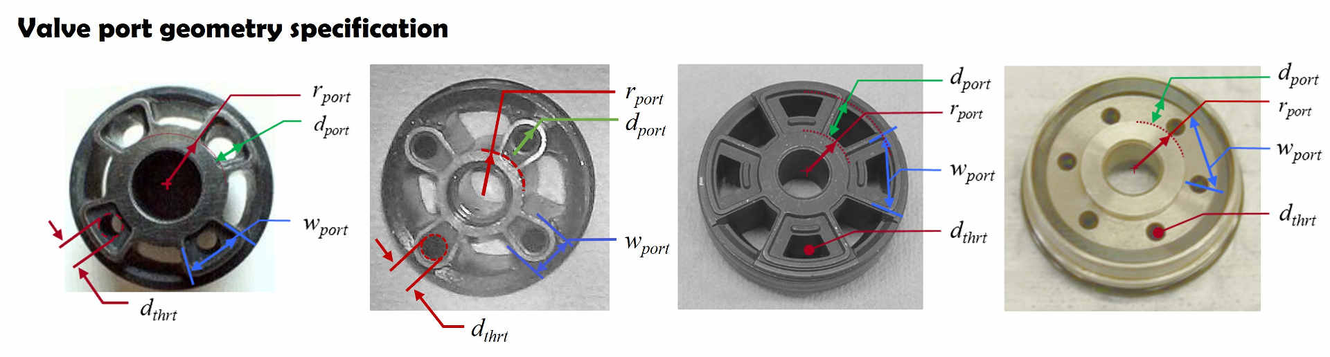
Valve port throat restrictions
Shock absorber valves often include a valve port throat flow restriction. The pressure loss from the flow restriction increases bottoming resistance and helps to linearize high speed damping curves (linky more info).
Shim ReStackor uses the d.thrt input to describe the port throat minimum flow area. The port throat can be re-tuned by filling in the port with JB weld and re-drilling the port with a smaller or larger diameter.
Shim stack controlled damping
Shock absorber shim stacks create the primary flow resistance through the shock absorber valve. Stiffer shim stacks require higher pressures to deflect the stack which increases the shock absorber damping force. Three parameters define the valve port geometry in Shim ReStackor calculations and control the resulting flow resistance.
- r.port: Port inside radius where fluid pressure is applied to the shim stack face
- d.port: Valve port spoke length controlling tangential spill out the valve port side
- w.port: Valve port perimeter seat length controlling radial perimeter spill
Port inward spill is limited by the r.port seat length and the small wedge shaped area where the flow dumps into the gap between ports. The size of the wedge shaped area depends on the stack stiffness, clamp diameter and r.port dimension.
Tangential side spill over the d.port spoke length is controlled by a wedge shaped flow area set by the shim stack edge lift, curvature of the face shim and the side port seat length defined by d.port.
The bulk of the valve flow dumps radially outward over the w.port seat length. However, the minimum flow area does not occur at the valve port edge.
Due to the curvature of the shim stack face shim the minimum flow area occurs on a conical surface extending normal to the shim stack face shim to the valve port inside edge. As the shim stack deflection increases the face shim curvature shifts the minimum flow area inward resulting in a nonlinear relationship between stack edge lift and flow area. The nonlinear relationship between shim stack edge lift and flow area is one of the reasons why shim factors poorly correlate shim stack stiffness with valve port flow area and shock absorber damping force.
Shim stack tuning
A tapered shim stack produces a digressive damping force curve. The blue line in the figure below is an example.
Adding a crossover softens low speed damping. Tuning the crossover position, gap and high-speed stack stiffness transitions the damping force curve into a linear damping force curve as shown by the green dashed line.
Using a larger diameter crossover positioned higher in the stack creates a damping force curve that matches the original tapered stack curve at low speed, but the lower digression rate produces more damping force at high speed.
Replacing the crossover with a preload ring-shim increases the low speed damping force and the overall damping force as shown by the read dashed line.
Using the ring-shim on a slightly softer shim stack matches the tapered stack damping force curve at low speed and softer damping at high speed as shown by the solid red line.
Tuning the shim stack stiffness, stack preload, crossover gap or ring-shim preload creates a endless range of tuning options with separate control of low and high speed damping. Shim ReStackor finite element analysis (FEA) of the shim stack stiffness produces a detailed accounting of the shim stack deflection, bend profile and the flow area computed using simple inputs listing the diameter and thickness of each shim in the shim stack (linky, phy FEA).
Shock absorber fluid dynamics
The damping force of shock absorbers is controlled through the combination of multiple fluid circuits. Valve port geometry, shim stack configuration, oil density, viscosity, temperature, bleed systems and back pressure devices suppressing cavitation all play a role in determining the shock absorber damping force. However, accurate fluid dynamic analysis is not enough to define shock absorber performance.
Shock absorber performance also depends on the stiffness and deflection of the shim stack which requires detailed FEA structural analysis to define the deflection and the flow area produced by the shim stack deflection.
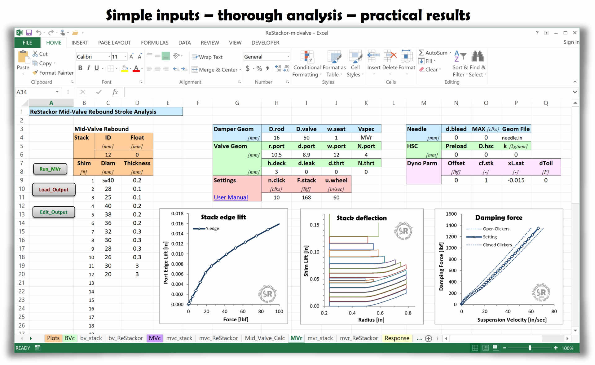
The combination of fluid dynamics and structural analysis creates a multi-physics problem. Solving the problem requires combining fluid dynamics, structural analysis and suspension response analysis into a single integrated multi-physics package. Shim ReStackor integrates those components into a simple to use spreadsheet based analysis tool providing the capability to fine tune suspension setups far beyond the limits previously possible.