There are two suspension motions of interest in shock absorber tuning.
- Wheel velocity from a bump impact
- Jump landing impact velocity
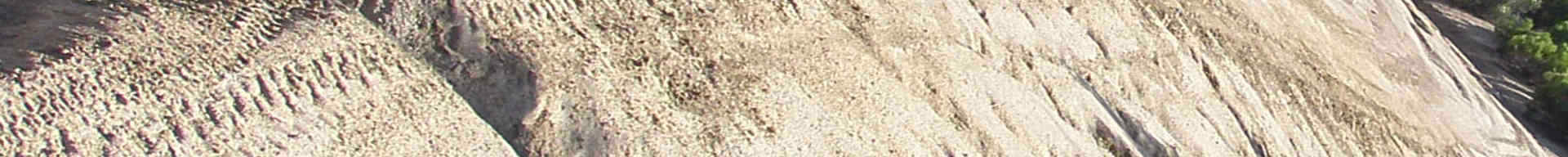
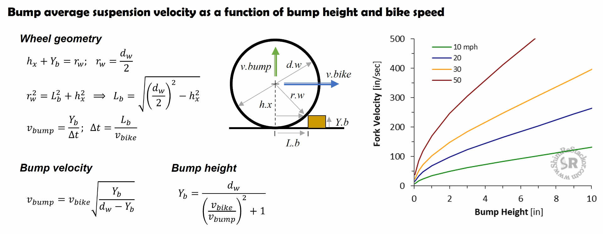
A wheel rolling over a square edge bump forces the hub to follow an arc like path over the bump.
With the simplifying assumption of a ridged wheel the geometry of the wheel defines the hub arc path and the resulting suspension velocity.
The bump velocity is highest at bump impact where the arc path is steep. The velocity asymptotically falls off as the wheel approaches the top of the bump.
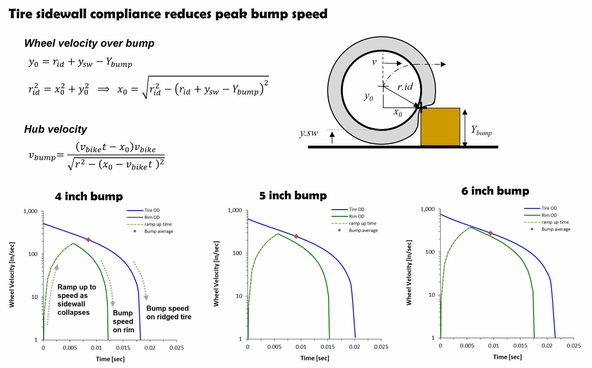
A more conservative estimate assumes the tire has perfect compliance allowing the sidewall to collapse on bump impact. With the tire collapsed, the rim diameter defines the hub arc path and resulting suspension velocity.
Tire compliance reduces the peak suspension velocity at bump impact and produces suspension velocities similar to the simplified bump averaged suspension velocities defined below.
Bump average velocity
Recommended approach
The simplest approach computes the average suspension vertical bump velocity dividing the bump height by the time required for the wheel to roll to the top of the bump.
The distance traveled from bump contact to the top of the bump is L.b. The time required for the bike to move that distance is t.bump = L.b/v.bike.
Over that time, the wheel has to move vertically by the bump height (y.bump) or the rim ends up with a flat spot.
Bump height divided by time defines the bump average velocity (y.bump/t.bump).
The bump average velocity is easy to estimate and in the ballpark of the more sophisticated methods defined above.
Test rides evaluate suspension performance in generalities like too soft or too stiff on notional “eye-balled” bump heights. Given the approximations simplified bump averaged suspension velocities are close enough to estimate suspension speeds for the purposes of retuning shim stacks.
Example bump velocity calculation
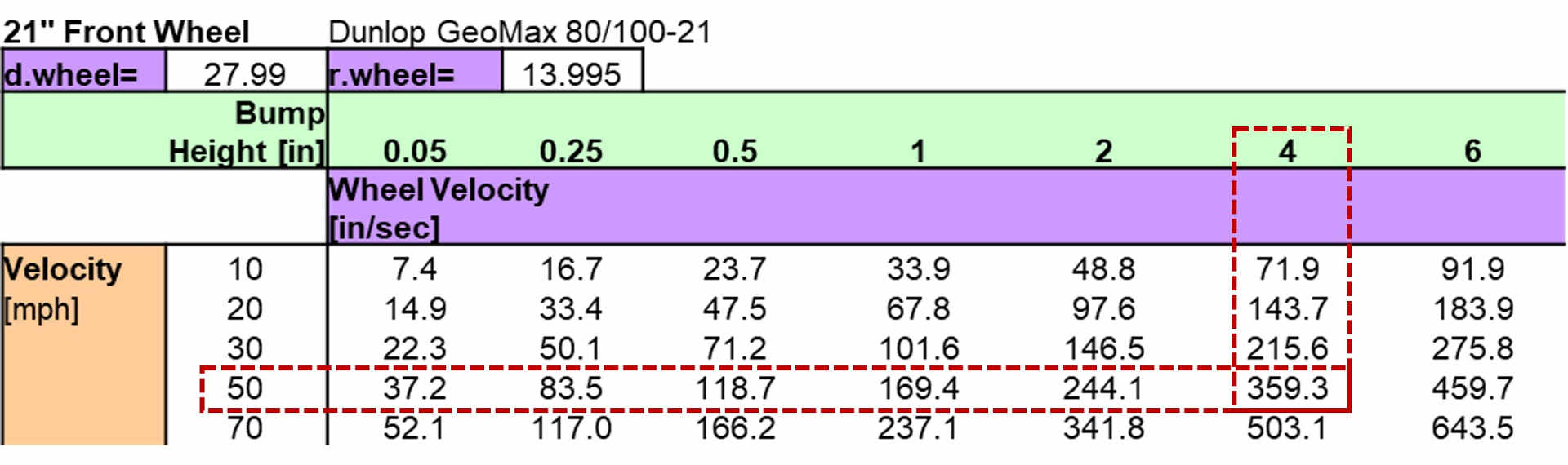
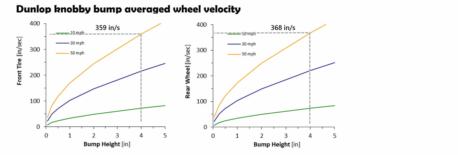
A 21 inch dirt knobby hitting a four inch bump at 50 mph produces a wheel bump speed of 359 in/sec.
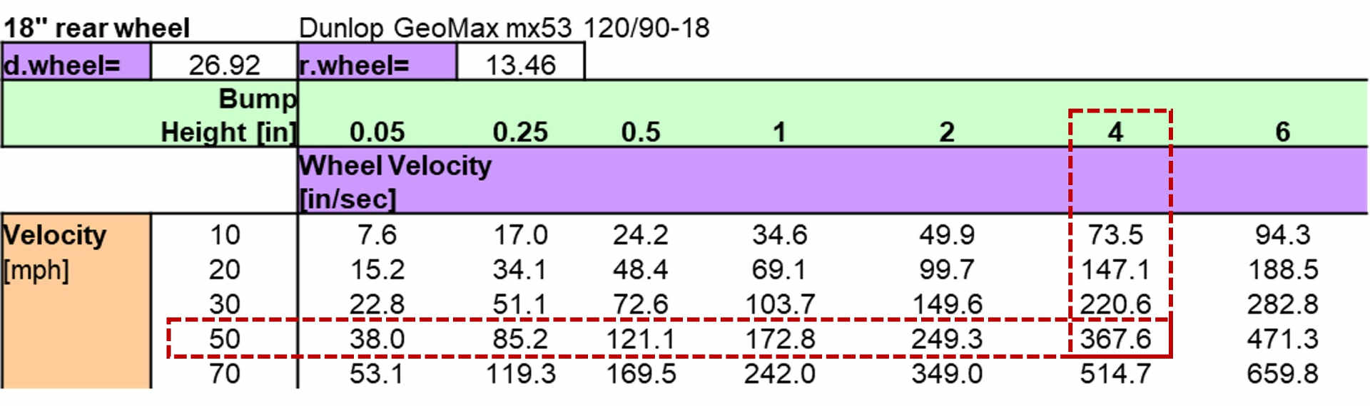
An 18 inch rear wheel knobby hitting the same bump at 50 mph produces a slightly higher bump velocity of 367 in/sec due to the smaller tire diameter.
Optimum fork bump angle
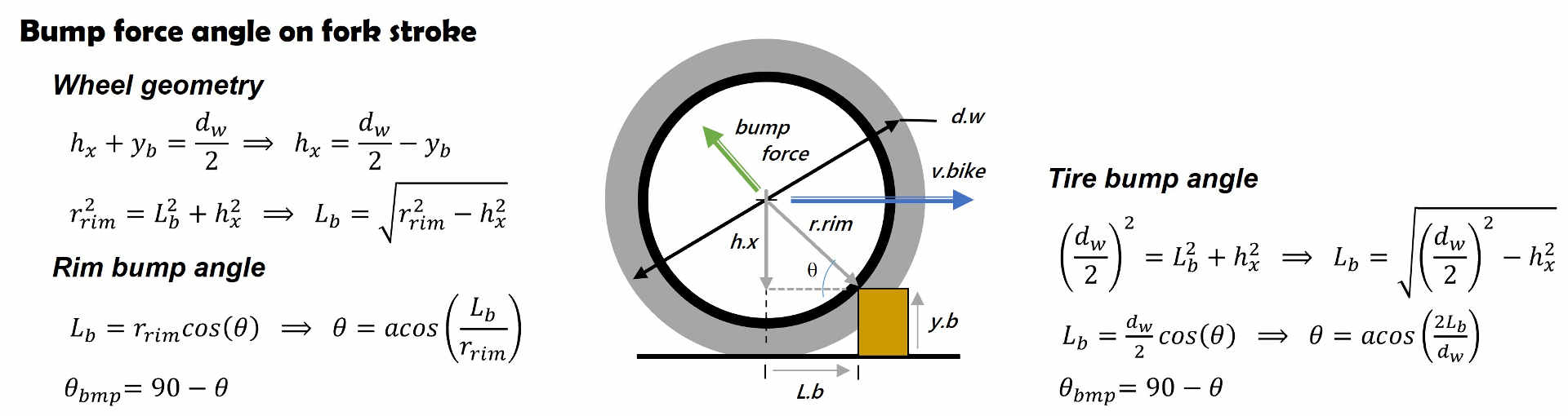
On bump impact, the contact point on the tire or rim transmits a force to the wheel hub. The angle of the transmitted force depends on the tire diameter and bump height.
If the bump force angle matches the fork rake angle the fork will smoothly move through the stroke. If the force angle is misaligned, the bump impact puts a side load on the fork bushings increasing the sliding friction and reducing fork compliance.
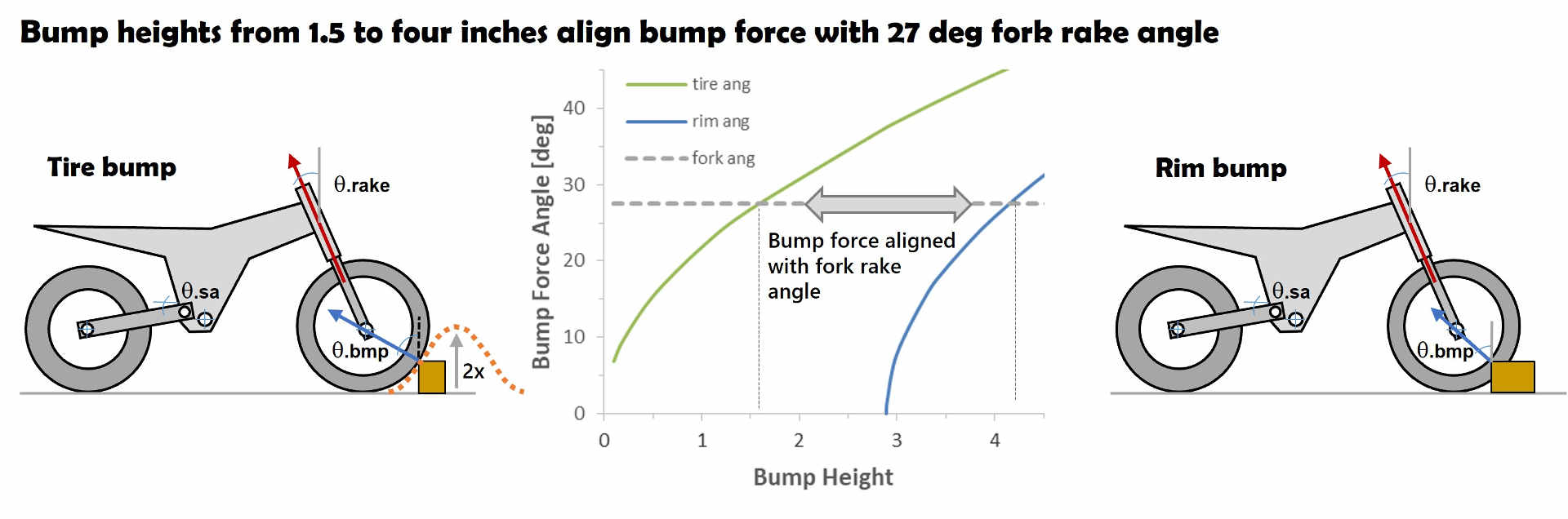
A bump height of 1.5 on the tire OD or 4.2 inches on the rim produces a bump force angle that lines up with a 27 degree rake angle.
If the bump is sinusoidal shaped, instead of square edged, the wheel contact point is roughly mid-bump. So the force angle on a 3 inch sinusoidal bump should align with the fork rake angle.
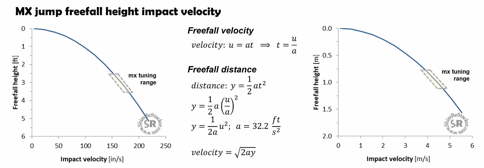
Jump landing velocity
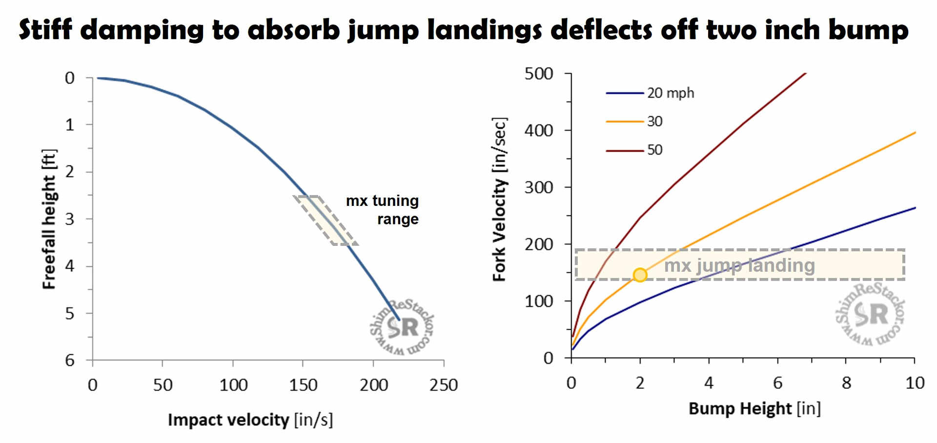
Gravity dictates jump landing velocities. A three foot freefall produces an impact velocity of 152 in/sec. Gravity dictates the freefall acceleration giving a direct method to estimate jump landing impact velocities.
Shim ReStackor suspension response calculations compute the suspension bottoming velocity based on the combined rider plus bike weight and the suspension spring rate, link ratio, gas force and compression damping.
Tuning a suspension to absorb a three foot jump landing simply requires hacking around on the compression shim stacks so the suspension is able to absorb the 152 in/sec impact velocity of a three foot jump landing (linky sec 3c).
Compression damping tuning compromise
A three foot jump landing and a 2.5 inch bump hit at 30 mph produce the same suspension velocity. Compression damping stiff enough to absorb the combined bike plus rider weight on jump landings will cause the chassis to deflect off a 2.5 inch bump.
To make hill climbs with roots, rocks or steps, enduro setups are forced to use softer compression damping to get the ground compliance and traction necessary to complete the hill climb.
MX setups are not competitive if the bike is not able to land a jump. Stiff compression damping required to land a three foot jump freefalls will deflect off 2.5 inch bumps hit at 30 mph.
The ground compliance necessary for an enduro setup and jump landing bottoming resistance requires for MX define the difference between MX and enduro suspension setups. The suspension cannot do both at the same time (linky sec 3d).