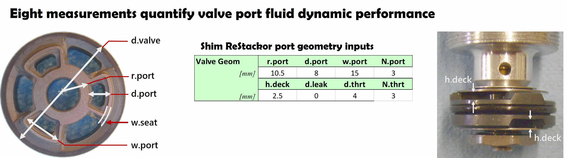
Three easily measured dimensions define the valve port geometry for ReStackor calculations:
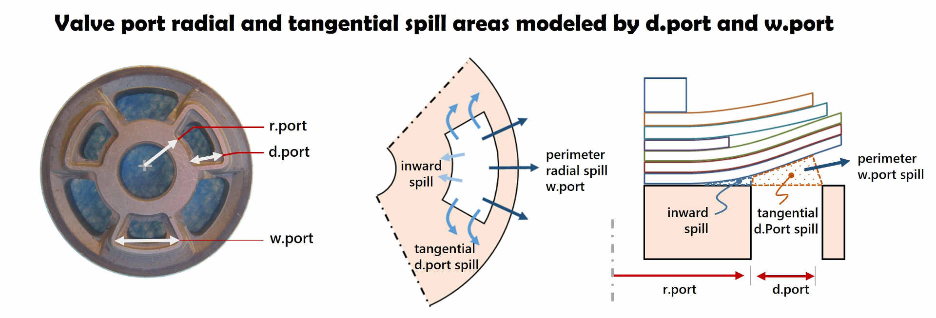
- r.port: Defines the inner radius where valve port fluid pressure is applied to the shim stack face
- d.port: Defines the valve port perimeter seat length metering radial outward spill
- w.port: Defines the valve port side length metering tangential spill out of the valve port
Additional parameters
- d.thrt: Valve port throat minimum flow area
- h.deck: Port inlet deck height
Valves with small deck heights between the valve deck and reverse flow shim stack use delta shims to space the reverse flow shim stack higher above the valve deck to increase the port entrance flow area.
Tuning the valve port throat area and inlet flow restriction controls the high speed bottoming resistance of the shock absorber.
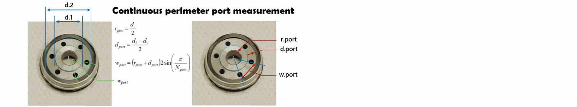
Continuous perimeter seat
For the special case of a continuous perimeter seat, like the compression adjuster valve shown below, the w.port perimeter length is arbitrarily parsed into six to eight segments to define the w.port width.
The number of segments is arbitrary, but typically defined to correspond with the number of inlet ports.
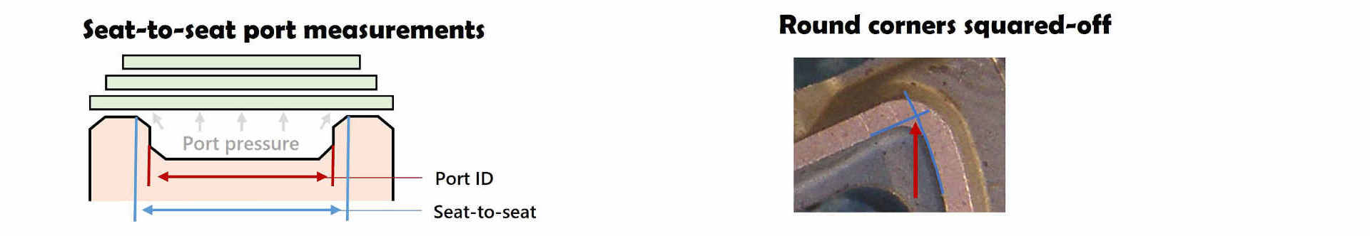
Shock absorber valves generally have sharp port edges making measurements easy. Rounded edges allow fluid pressure to act on the shim stack face up to the location of the seat. The increased pressurized face area increases the fluid force acting on the shim stack increasing the stack deflection.
Measurements of r.port, d.port and w.port need to account for rounded seat edges by measuring the seat-to-seat distance. Likewise, w.port and d.port measure the seat length up to the imaginary intersection of the valve port side and perimeter seat which squares off the rounded corner.
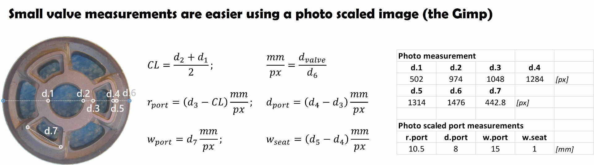
Small diameter valve measurements
On small valves enlarged photographs of the valve are an easier way to measure the port dimensions. To get accurate measurements the photograph needs to be taken directly over the valve using a camera lens without “fish-eye” effects. Lens fish-eye can be checked by photographing a piece of graph paper to make sure boxes on the edge of the photograph have the same dimensions as boxes in the center.
Changing camera zoom can correct or create fish-eye distortions. Dimensions on the photograph below were measured using “the gimp” image manipulation program with dimensions scaled using the valve outside diameter measurements.
Critical performance parameters
The ReStackor dimensions of r.port, d.port and w.port define the valve port perimeter seat length, flow area and shim stack pressurized face area applying fluid force to the shim stack.
Shim ReStackor uses those three parameters to define the valve port flow area, A.port. The perimeter spill length, P.spill and the torque based center of fluid pressure cP. Those valve port parameters developed for use in ReStackor have also been adopted for other modeling studies. (P. Skackauskas, Vilnius Gediminas Tech Univ, 2016).
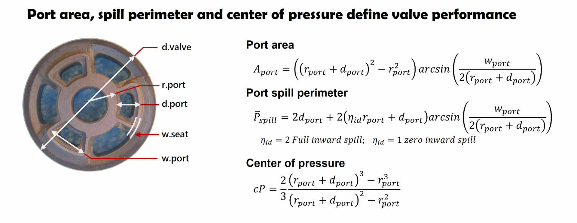
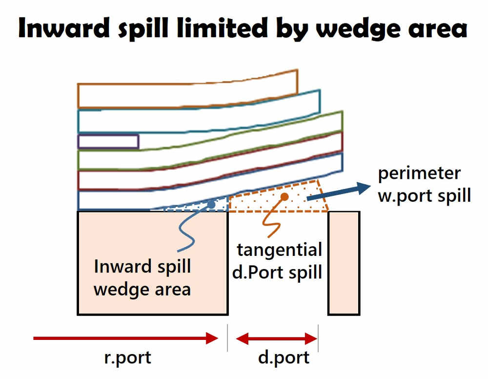
Fluid inward spill is metered by the valve port inside radius r.port and sweep angle defined by the edge w.port length. Inward spill is generally limited by the wedge shaped spill area formed between the valve deck and deflected shim stack. In the above equation the parameter n.id defines the inward spill effectiveness.
A n.id value of two is full inward spill limited only by the port inside perimeter. A n.id value of one gives zero inward spill. Shim ReStackor automatically determines the value of n.id based on internal calculations evaluating the valve port geometry inputs.
Difficult port geometries
Some valve port geometries do not have a simple definition of r.port, d.port and w.port. The port flow area and perimeter seat length for those configurations are estimated through combinations of circles, rectangles and triangles to determine the effective valve port flow area.
With valve port flow area and seat perimeter length estimates the “effective” dimensions of r.port, d.port and w.port are determined to match the critical parameters of A.port, P.spill and cP as shown in the example below.
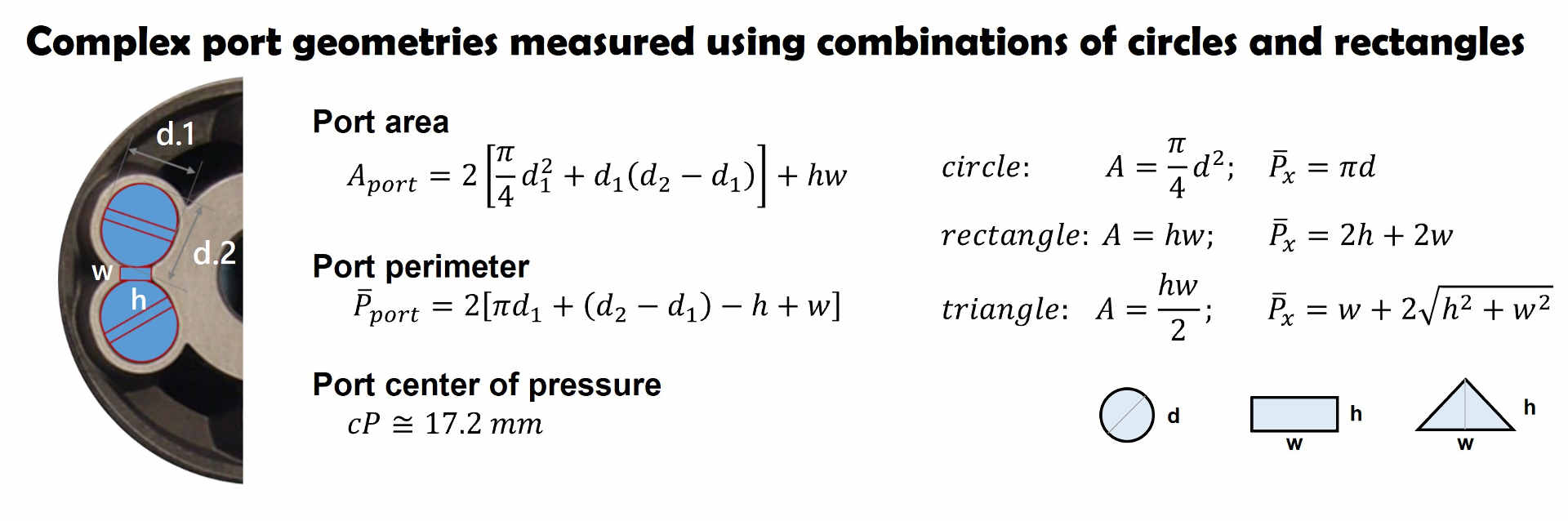
The r.port, d.port and w.port values determined for the above port geometry do not correspond to any measurable dimension. But, the combination of those parameters match the valve port flow area, perimeter length and center of pressure.
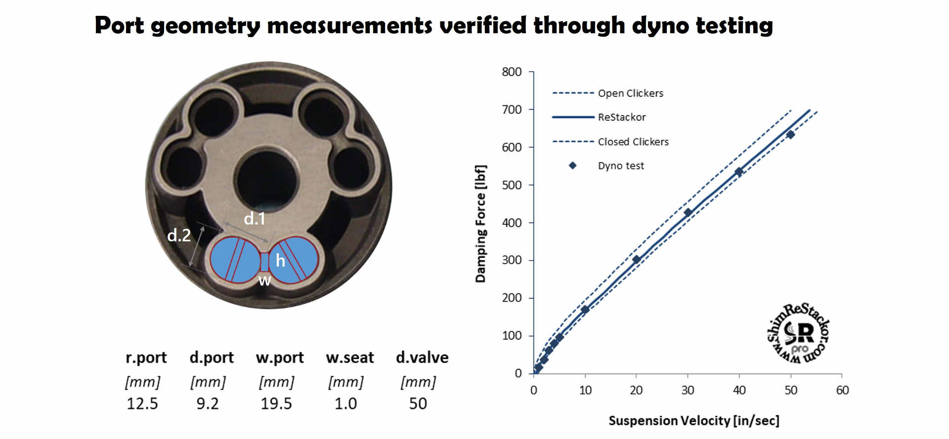
The most direct way to determine the accuracy of the deduced port dimensions is comparison of the computed damping force values to measurements of a dyno. For the above example, the results provide a close match.
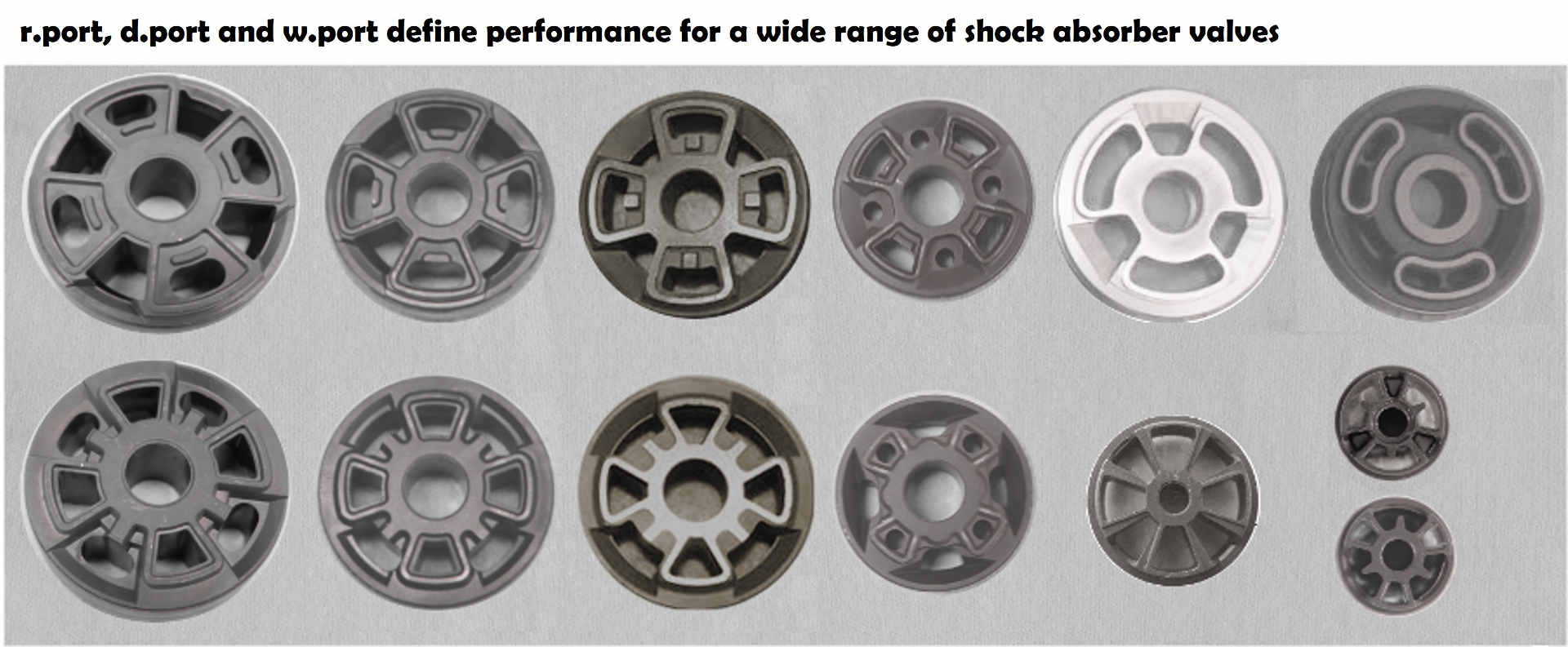
Shock absorber valve port geometry
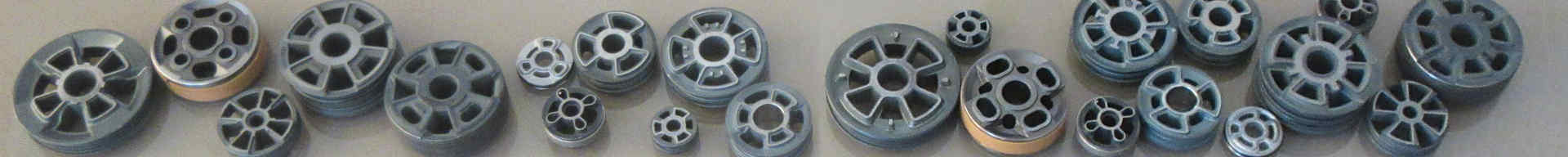
Shock absorbers use many different styles of valve port geometries. Manufacturing convenience dictates some geometries. Others are designed around the use of throat restrictions for control of high speed flows. Regardless, three parameters define damping performance:
- Pressurized face area defining the fluid force applied to the shim stack
- Center of pressure defining the torque of the applied force
- Valve seat perimeter length metering the fluid flow
The Shim ReStackor input parameters r.port, d.port and w.port define those parameters using simple geometric measurements applicable to a wide range of valve port geometries.