Linked suspension systems change the ratio of wheel to shock motion and that ratio changes through the stroke.
The two parameters Travel ratio and Link ratio describe the change in motion and force transfer through linked suspension systems.
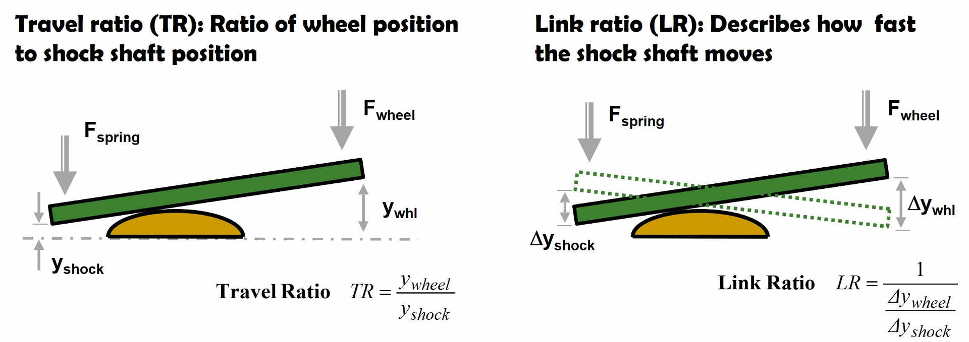
Travel ratio (TR)
Travel ratio is the ratio of wheel to shock shaft position. Travel ratio defines how far the spring is compressed at a given wheel position which defines the spring force.
Link ratio (LR)
Link ratio defines the change in shock shaft position for a minute micro motion of the wheel. Link ratio defines how fast the shock shaft moves and that defines damping force.
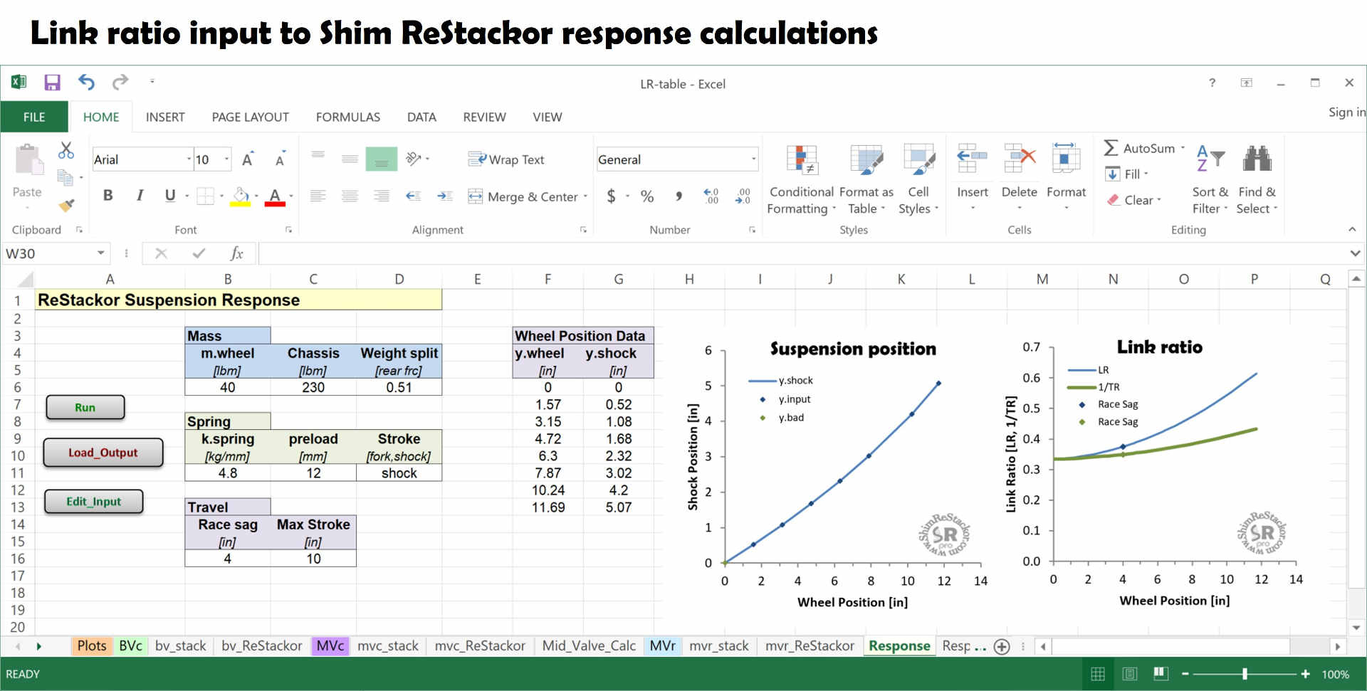
Travel ratio defines the shock shaft position. Link ratio defines the shock shaft velocity. The two ratios are similar but the numerical values are different as demonstrated in the graph below. Shim ReStackor response calculations compute the suspension link ratio from inputs of measured wheel and shock shaft position.
Measuring the wheel and shock shaft positions through the stroke provides a simple and direct method to determine the suspension link ratio and an easy way to compensate for year-to-year changes in the suspension setups or the effect of custom link arms and aftermarket knuckle geometries.
Spring force at wheel
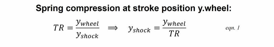
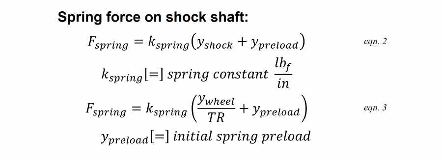
To get spring force at the wheel, the first step is figure out how far the spring is compressed when the wheel is moved to a specific stroke position y.wheel. Travel ratio specifies the relationship.
The spring constant and spring preload (y.preload) define the spring force on the shock shaft.
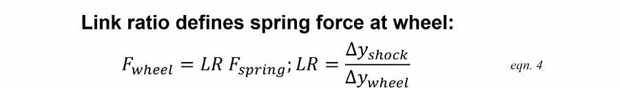
A simple teeter-totter torque balance defines force amplification through the link system. The suspension link ratio (LR) specifies how far the spring moves for an incremental change in wheel position, which also defines the teeter-totter force transfer through the suspension link to the rear wheel.
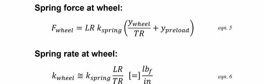
Combining the link ratio and travel ratio equations gives a single equation specifying the spring force at the wheel given any wheel position y.wheel.
Damping force at wheel
Link ratio (LR) defines the ratio of shock shaft to wheel velocity.
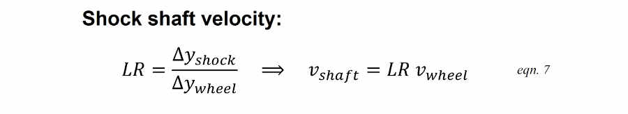
Damping force at the shock shaft is defined by the shock shaft velocity and damping coefficient. When combined with the above link ratio relationship the damping force at the shock shaft can be computed directly from the wheel velocity.
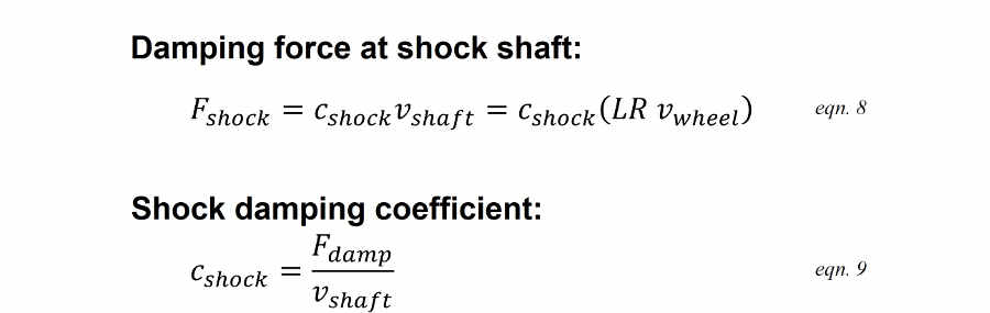
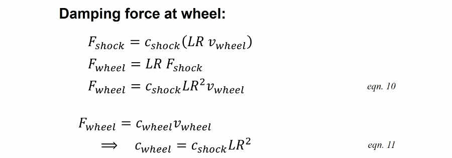
The same teeter-totter torque balance used for spring force defines the damping force transfer to the wheel. Combining the relationships gives a single equation defining damping force at the wheel given a specified suspension wheel velocity. The relationship also defines the shock damping coefficient at the rear wheel in terms of rear wheel bump velocity, c.wheel.
Link ratio spring force progression
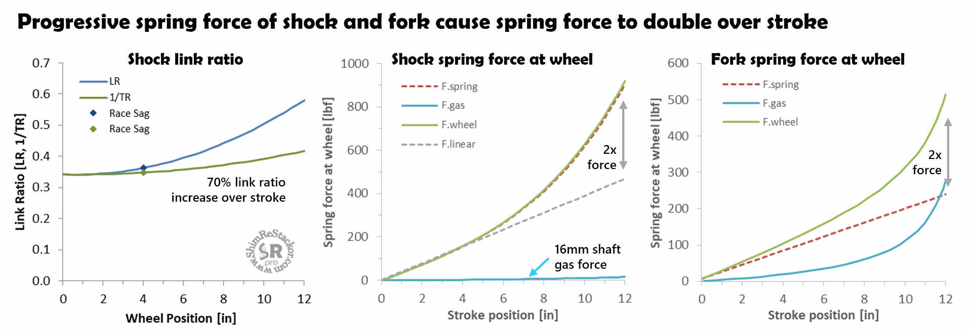
Linked suspension systems produce a progressive spring force increase through the stroke. Link ratios used in dirt bikes change from bike-to-bike and year-to-year but stay within a narrow range producing approximately a factor of two increase in spring force through the stroke.
The example below uses a typical MX link ratio demonstrating the spring force increase at the rear wheel. The shock bladder gas force computed by Shim ReStackor has little effect on the overall spring force.
Fork spring force computed by Shim ReStackor includes the main spring, ICS system and gas spring force. Running stock oil levels shows the fork spring force also increases by approximately a factor of two over the stroke.
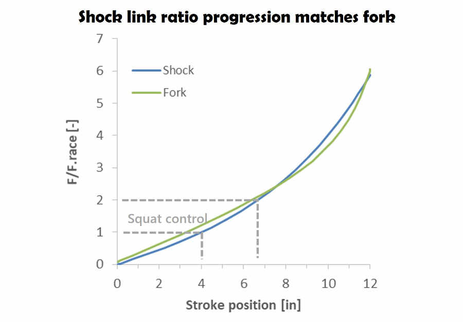
Normalizing the two curves with the spring force at race sag shows the spring force progression from the rear shock link ratio approximately matches the fork gas spring progression. Matched front/rear spring force gives the suspension a balanced “feel”.
Thus, link ratio is not a random variable. It is specifically set to match the fork spring progression rate. Likewise, the fork oil level is specifically set to match the shock like ratio.
Non-linked suspension systems use progressive springs to approximate the same effect.
Linked suspension damping
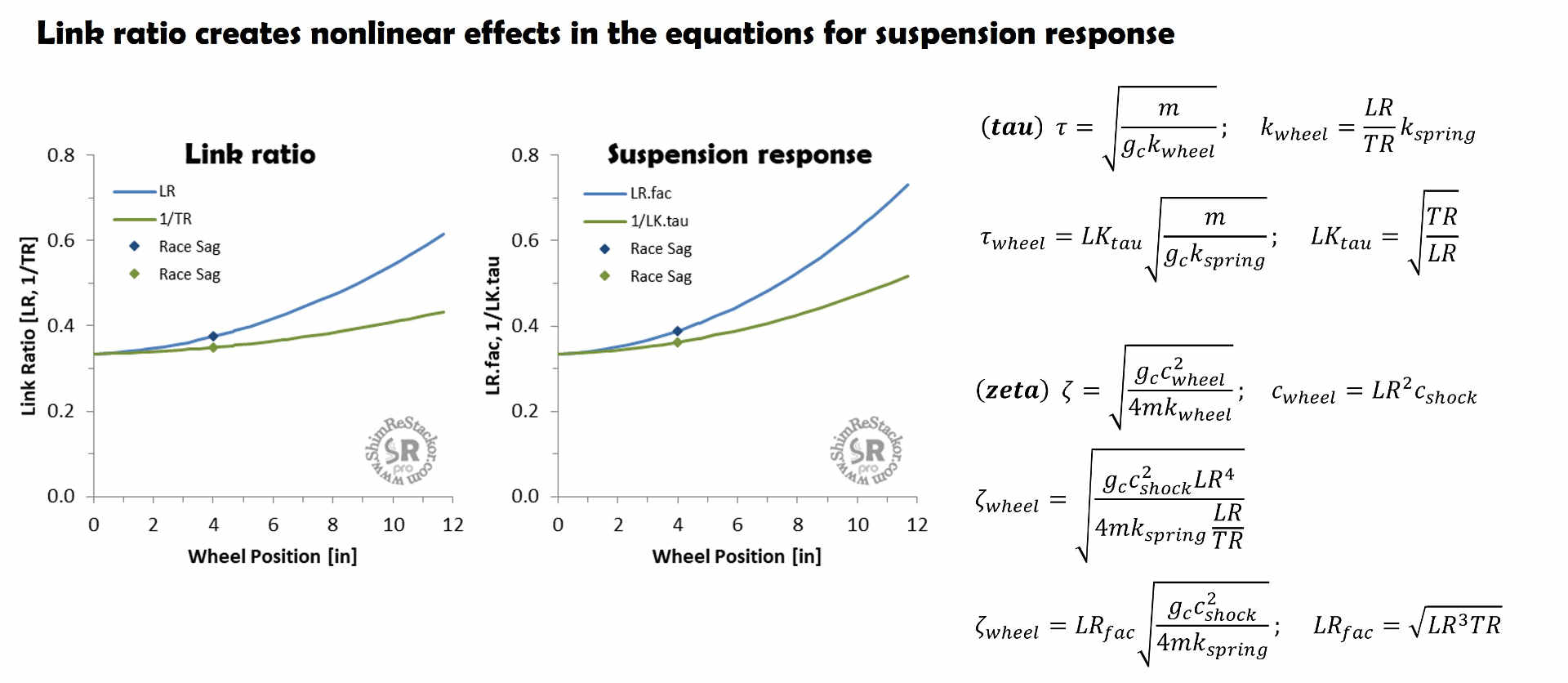
Spring-mass-damper theory defines the effect of spring rate and damping on suspension response for the special case of linear spring rates and damping. Linked suspension systems make both of those terms nonlinear.
Link ratio modifies the relationship for tau by the sqrt(TR/LR) which decreases with stroke depth. Tau defines the time required for the suspension to return to race sag. The decrease in tau with stroke depth causes the spring force to increase deeper in the stroke shortening the time required for the suspension to return to race sag.
The equation for zeta is modified by LR.fac= sqrt(TR*LR^3). Zeta defines damping performance and the increase in the LR.fac term with stroke depth drives the suspension into an overdamped condition when pushed deeper in the stroke.
The nonlinear spring and damping force terms created by link ratio require numerical integration of the suspension stroke to account for the continuously change link ratio. Shim ReStackor performance that integration.
Linked suspension response
The nonlinear terms created by a linked suspension systems cause the suspension to flip from under to overdamped conditions as the suspension moves through the stroke. The increasing gas spring force in a fork creates the opposite effect. There is no simple algebraic way to integrate the nonlinear terms through the stroke to determine the overall suspension response.
The nonlinear effects require numerical integration through the suspension stroke, stepping through the suspension stroke a microsecond at a time, evaluating the forces acting on the suspension, the resulting acceleration and stroke averaged suspension response. Shim ReStackor calculations provide that integration.
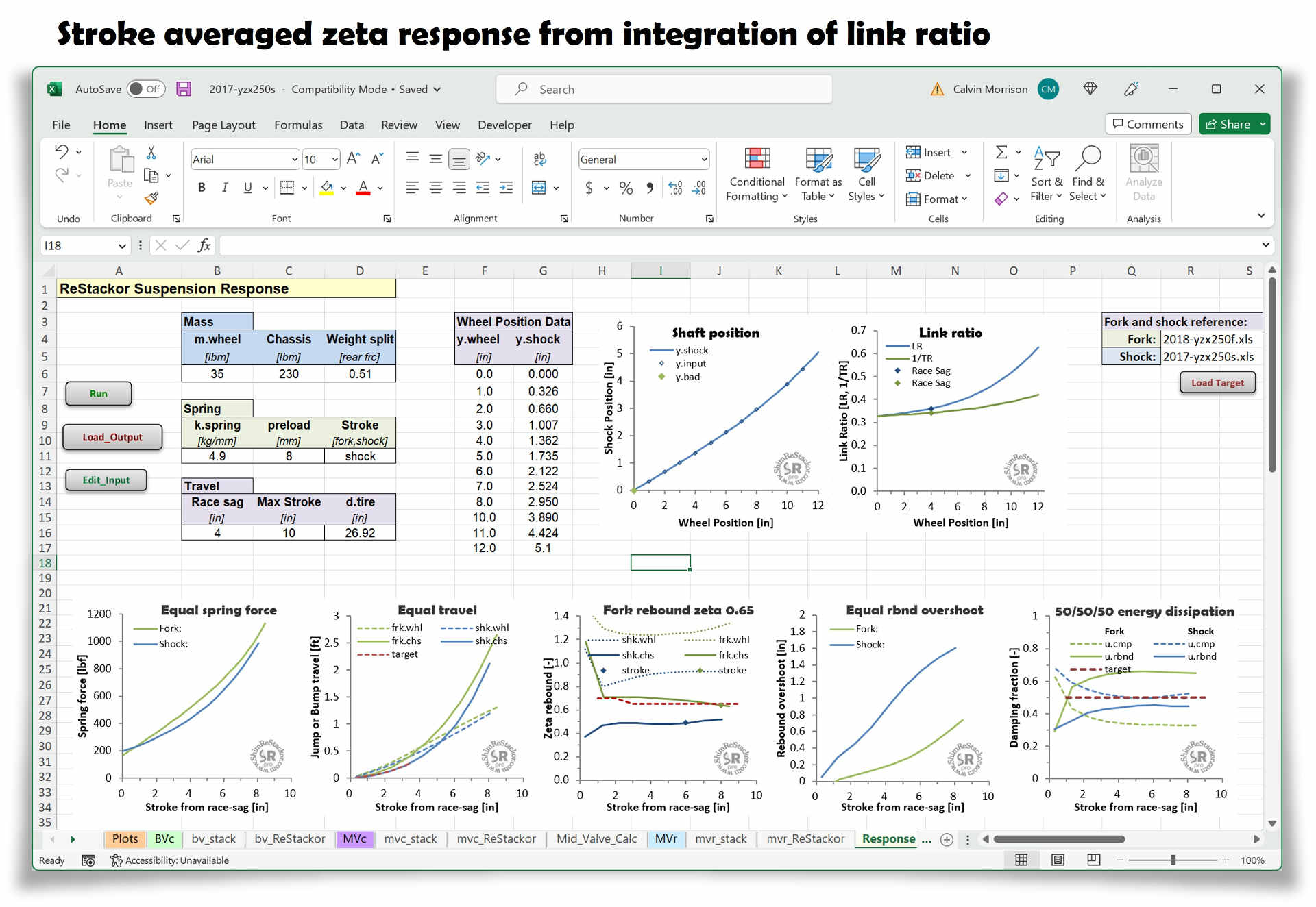
Rebound damping zeta values in the screen shot below are too soft at the lower speeds of short suspension strokes. Fixing the setup requires retuning of the rebound shim stack crossover to provide more low-speed damping to produces a consistent zeta 0.7 value across the range of stroke depths.
Tuning damping force curves to deliver a consistent suspension response simply requires hacking around on the shim stack crossover position, thickness, diameter and bleed system to deliver a constant zeta value across the range of suspension stroke depths. Nonlinear effects in the damping curve, link ratio and gas force are accounted for in the Shim ReStackor numerical integration of the suspension stroke (linky sample apps rbnd).