The physics of F=ma dictates suspension response. Force (F), the first term, is the combination of spring force plus damping. Mass (m) is the suspension wheel or chassis weight depending on which body you want to evaluate. The final term, acceleration (a), describes the suspension velocity and position as a function of time.
Spring-mass-damper theory applies the basic physics of F=ma to the special case of linear springs with linear damping to derive the algebraic equation defining suspension response, the damping stiffness needed to control suspension stroke depth and optimum rebound response needed to suppress suspension resonance. (linky sec 1.1.1).
In actual suspension systems the spring force is nonlinear due to the suspension link ratio as well as the gas force from the shock absorber. The damping force is also nonlinear due to the nonlinear velocity squared relationship inherent in fluid dynamics. Quantifying nonlinear response requires stepping through the suspension stroke, a microsecond at a time, summing up all of the forces acting on the suspension at that instant to evaluate the resulting F=ma acceleration. With acceleration known, the change in velocity and position can be computed and the calculations advanced to the next microsecond in time to evaluate the forces acting on the suspension at the new velocity and position.
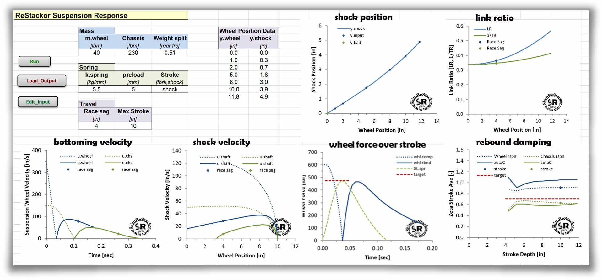
Shim ReStackor performs that nonlinear integration to define the response and bottoming resistance of practical suspension systems using nonlinear link ratios and nonlinear damping.
Suspension link ratio
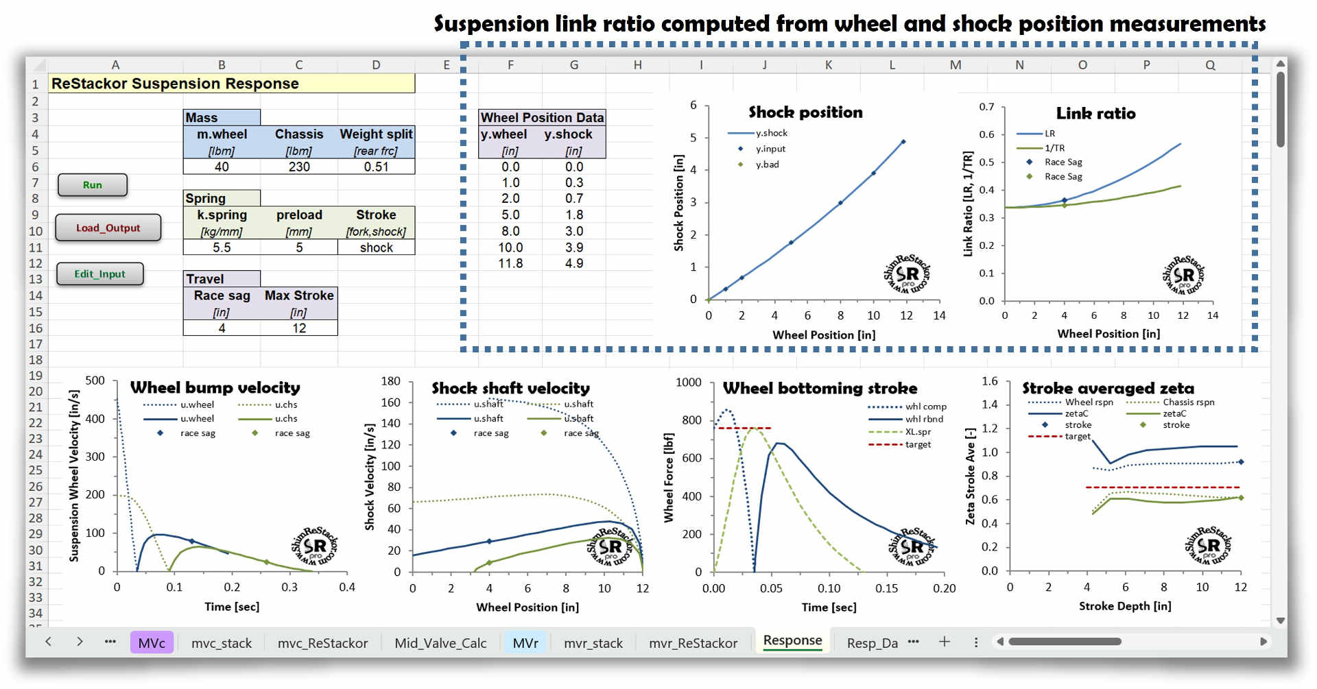
Shim ReStackor computes the suspension link ratio from inputs of measured wheel and shock shaft position. Inputs of spring rate and preload define the spring force and inputs of fork oil level, ICS configuration and shock gas reservoir pressure define the gas force. Shim ReStackor combines the above inputs with link ratio to compute the suspension force at the wheel and the resulting suspension response.
Using inputs of the shim stack configuration and valve port geometry Shim ReStackor computes the fluid dynamic forces controlling compression and rebound damping. Shim ReStackor also computes seal drag and the increase in seal drag with pressure inside the shock chambers.
Tuning the suspension bottoming resistance with Shim ReStackor is a simple matter of adding or removing shims from the shim stack and recomputing the shock absorber performance and suspension response system to achieve the desired bottoming resistance.
Suspension bottoming
There are two ways to bottom a suspension:
- Hit a bump hard enough for the wheel to blow through the stroke and bottom
- Land a jump hard enough for the combined chassis plus rider weight to crush through the compression stroke and tap bottom
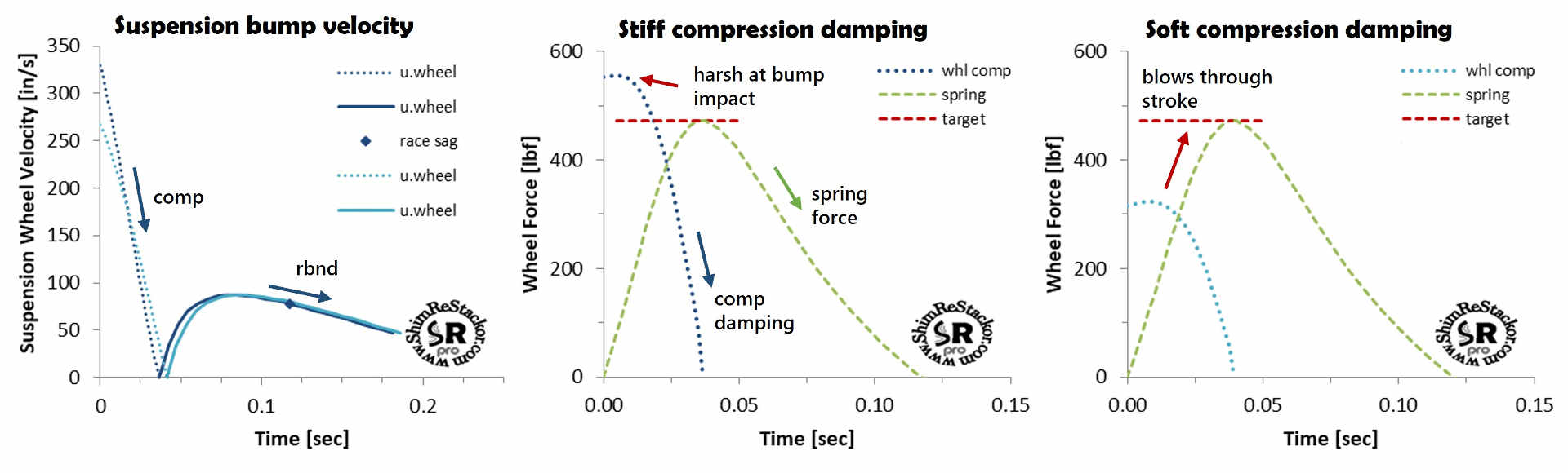
Wheel bottoming velocity
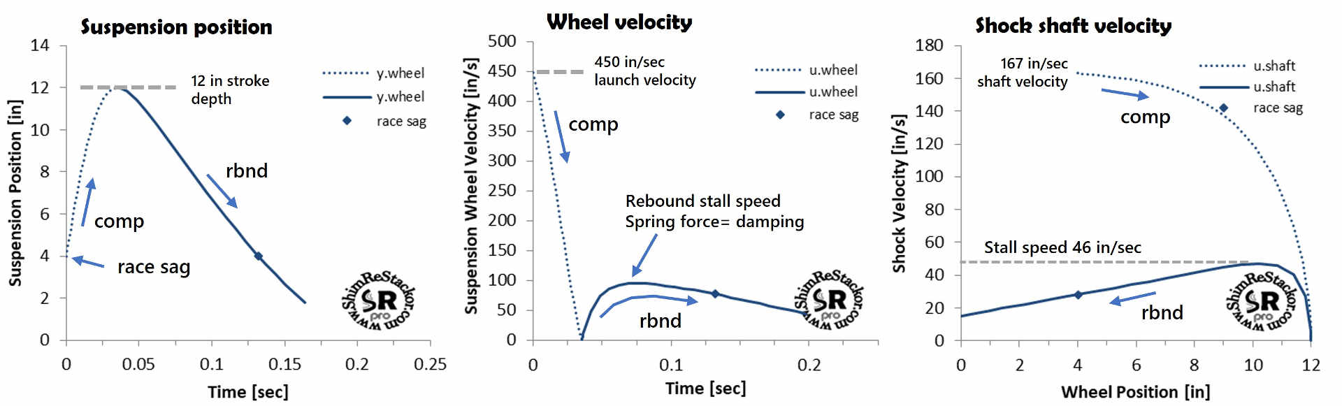
The “Max Stroke” input specifies the stroke depth evaluated. Internal calculations determine the bump launch velocity needed for the wheel weight to blow through the compression stroke and hit the target “Max Stroke” depth. For the example below, a wheel bump velocity of 450 in/sec is required to push the suspension into a 12 inch stroke. On the bottoming stroke, the maximum shock shaft velocity is 167 in/sec set by the suspension link ratio. There is no point in tuning the shock absorber beyond that velocity as the suspension is bottomed.
From the “Max Stroke” depth at 0.04 seconds, the calculations continue into the rebound stroke hitting the maximum rebound speed at 0.065 seconds. As the suspension approaches the maximum rebound speed the shock absorber damping force becomes equal to the suspension spring force producing a stall speed. As the suspension extends beyond that point the drop in spring force reduces the suspension velocity which also reduces the shock absorber damping force.
On the twelve inch bottoming stroke the maximum rebound shock shaft velocity is 46 in/sec. There is no point in tuning rebound damping beyond that shaft speed as the suspension cannot reach those velocities.
From bump impact the suspension requires 0.13 seconds to return to race sag. At 30 mph the bike travels 5.5 feet over that time interval. Bumps spaced closer than that will pack the suspension.
Chassis bottoming velocity
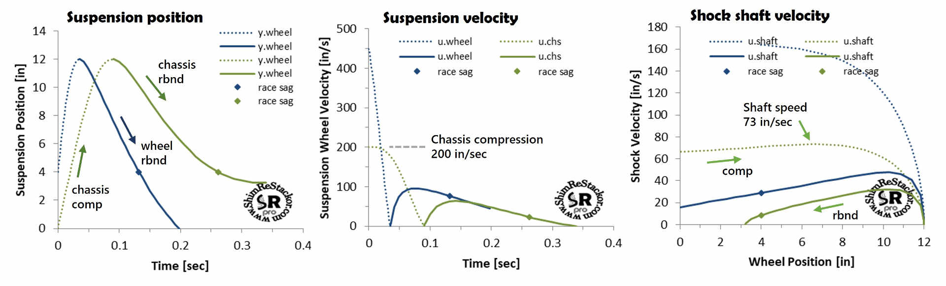
The second way to bottom a suspension is hitting a jump landing hard enough for the bike plus rider weight to crush through the compression stroke and tap bottom. Chassis bottoming on a 12 inch suspension stroke is shown by the green curves in the example below. Bottoming the chassis requires an impact velocity of 200 in/sec equivalent to a 4.3 foot jump free-fall (linky free-fall velocity). The maximum shock shaft velocity on the bottoming stroke is 73 in/sec. Modifying the spring rate or damping changes the bottoming velocity.
Chassis bottoming defines the low speed velocity range of the shock absorber. Wheel bottoming defines the upper limit of high speed damping. Those velocities are specific to the spring rate and rider weight used. Knowing shaft velocities that control jump landings and the higher velocities controlling wheel bottoming allows customization of the damping force curve to target specific ills of the suspension setup.
Force over stroke
The compression damping force is highest at bump impact and drops off as the suspension slows through the stroke. On the other hand, spring force ramps up through the stroke reaching a maximum at end of stroke.
Suspension setups where compression damping is t00 stiff produce a bump impact force that is higher than the peak spring force. That produces a bang at bump impact followed by a drop off in compression force as the suspension approaches the lower peak spring force at end of stroke.
Compression damping that is too soft produces a bump impact force that is less than the peak spring force. That allows the suspension to “blow through” the bump impact into the stiffer spring force at end of stroke.
“Plush” balances the two extremes producing a compression damping bump impact force that matches the end of stroke spring force. Matched peak force produces a nearly constant force through the stroke with compression damping dropping off as the spring force ramps up to keep the overall force approximately constant. Constant force through the stroke absorbs the maximum bump energy while minimizing the g-force transferred to the rider.
Setting compression damping to match the peak spring force is a simple matter of hacking around on the compression shim stacks to line up the peak compression damping force with the peak spring force. Response calculations also quantify small bump performance allowing tuning of crossover gaps to improve wheel traction (linky comp damping).
Rebound tuning
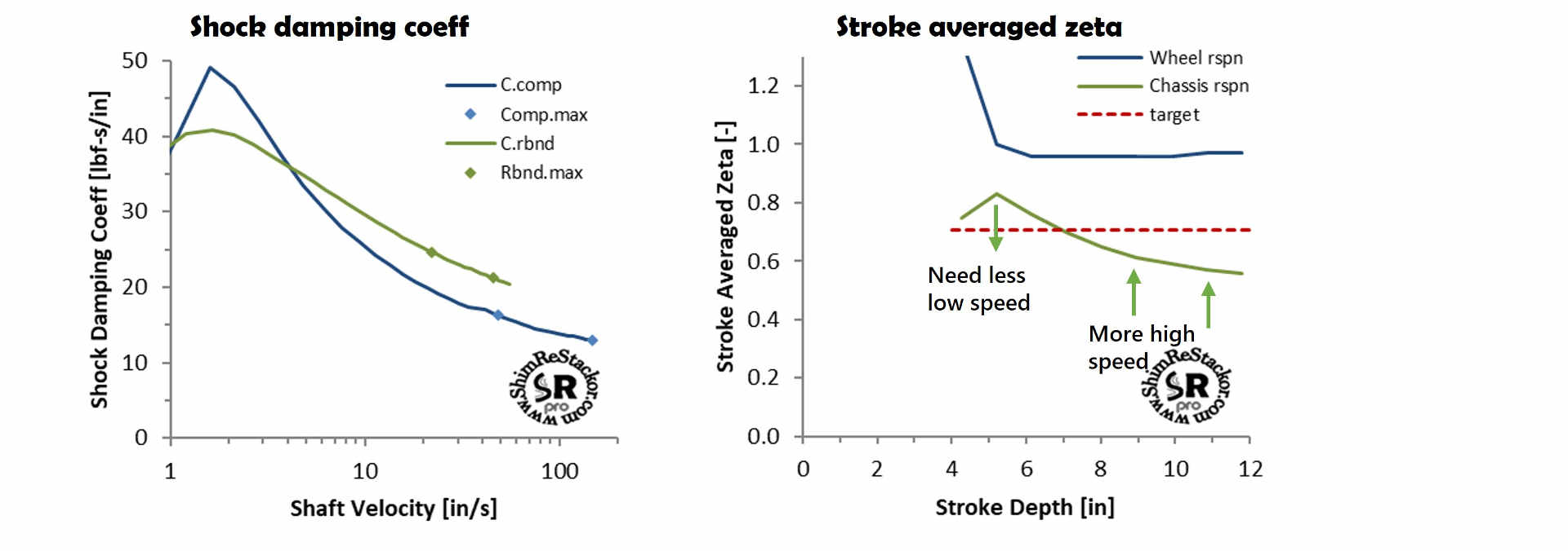
Spring-mass-damper theory defines zeta 0.7 rebound damping to provide the fastest possible rebound response with damping that is still stiff enough to suppress suspension resonance. However, spring-mass-damper theory is based on linear damping. Actual suspension systems have nonlinear link ratios, nonlinear damping and a nonlinear gas spring force. Applying spring-mass-damper theory to nonlinear systems requires definition of a stroke averaged damping coefficient.
Shim ReStackor defines the stroke averaged zeta coefficient as the ideal spring-mass-damper zeta value that matches the nonlinear system response time and final velocity on return to race sag. Shim ReStackor computes the nonlinear stroke averaged value starting with short strokes around race sag and continuing to progressively deeper strokes up to the maximum stroke depth specified by the link ratio input table.
The calculation outputs produce a table of stroke averaged zeta values starting at race-sag and continuing up to the suspension bottoming limit. Obtaining a consistent suspension response, “feel” and behavior across the stroke range requires a near constant zeta coefficient across the range of suspension stroke depths.
The example below shows rebound damping is too stiff for short strokes around race-sag and too soft on deeper strokes. Correcting the behavior to obtain a near constant stroke averaged zeta value across the stroke range requires modifying the shim stack crossover to produce less damping at low speed (two inch strokes) along with a stiffer high speed stack to increase rebound damping on deeper strokes.
Suspension response tuning
The basic physics of F=ma dictates suspension motions. Shim ReStackor combines inputs of spring rate, link ratio, gas force, bike weight, rider weight and damping computed from the shim stack configuration to determine the suspension response and performance.
Calculation results quantify bump velocities that bottom the wheels and jump landing impacts that bottom the chassis. Detailed outputs quantify spring force and damping over the stroke providing specific tuning targets needed to create a balanced and well damped “Baseline suspension setup” (linky, sec 3b1).