Suspension oil viscosity is specified in terms of kinematic viscosity defined as the actual viscosity (aka dynamic viscosity) divided by the oil density in the units of centi-stokes at a specific temperature, 20 cSt@40c.
The definition of kinematic viscosity as the ratio of viscosity to density creates some confusion in suspension tuning that few understand.
Shock absorber damping force depends on both oil viscosity and density:
- High viscosity increases flow losses driving damping force up
- High density oils require more force to push the heavy fluid through flow restrictions resulting in increased damping force
A high density oil will produce more damping force, but the value of kinematic viscosity will be lower due to the viscosity/density definition.
By itself, kinematic viscosity means nothing. To determine the shock absorber damping performance both the viscosity and density must be known.
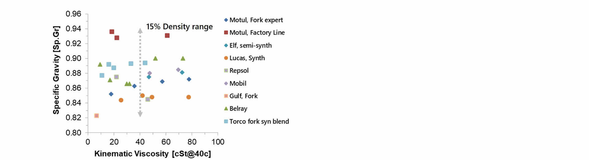
Oil density
Brand-to-brand oil densities vary by 15%. Low density oils produce less damping force because the oil weighs less requiring less force to push the oil through flow restrictions. But, a low density oil will have a high value of kinematic viscosity due to the viscosity/density definition.
By itself, the kinematic viscosity printed on the side of a suspension oil bottle means nothing without knowing the density.
Specifying the true oil dynamic viscosity in centipoise (cP) would be a better oil specification, but that standard is not used.
Clicker bleed performance
Kinematic viscosity becomes even more confusing when comparing different fluid circuits. Most suspensions use a simple conical needle in the clicker circuit. High fluid acceleration at the throat makes tapered needles sensitive to fluid density.
Other clicker circuits use friction needles. Friction needles have a small needle taper. Screwing the needle in increases the length of the high velocity throat region and the longer length increases viscous friction losses. Friction needles are sensitive to oil viscosity and relatively insensitive to density.
Viscosity and density effect fluid circuits in different ways. Both viscosity and density must be separately evaluated to determine the effect of oil properties on damping performance.
Shim ReStackor makes those calculations and accounts for brand-to-brand differences in oil density and viscosity to determine the overall effect on damping performance .

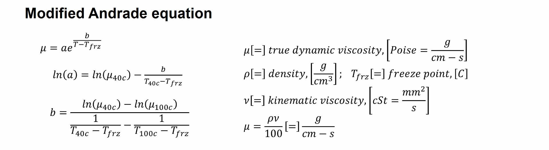
Viscosity falloff with temperature
ReStackor evaluates the viscosity temperature falloff using the Andrade equation. Manufactures specify oil properties at two temperatures cSt@40C and cSt@100C. When combined with density, those properties define the true dynamic viscosity and the Andrade equation coefficients needed to correct oil viscosity for changes in temperature.
The oil viscosity computed by Shim ReStackor exactly matches the manufacture specs at 40 and 100 C. The Andrade equation scales those oil viscosity to intermediate temperatures and accurately extrapolates those oil viscosities to temperatures beyond the oil spec range.
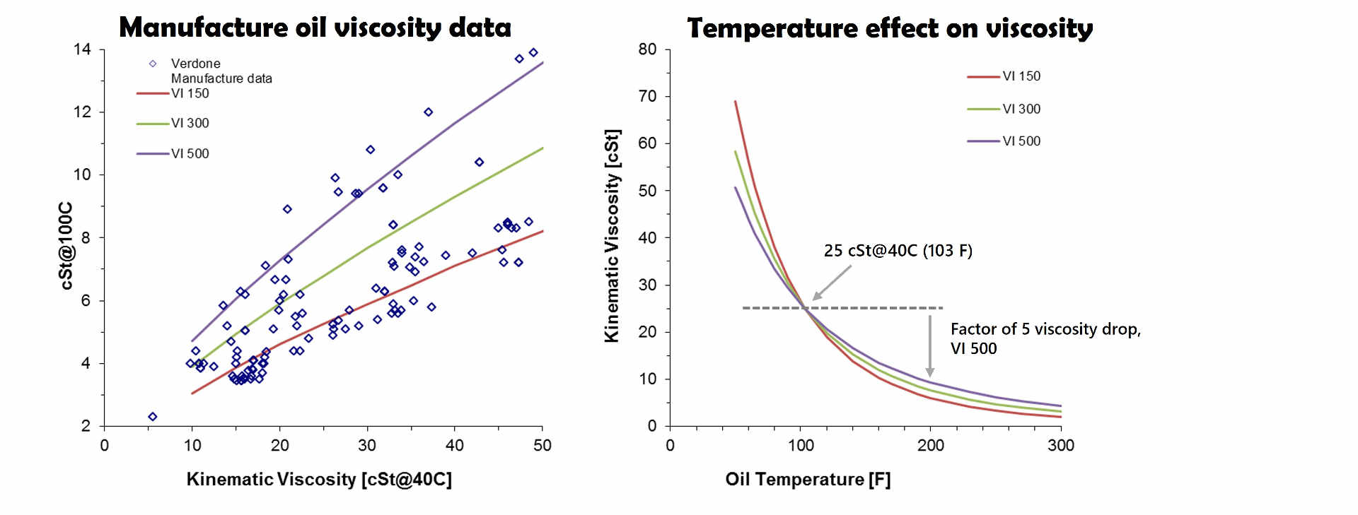
The Viscosity Index (VI), defined by ASTM D 2270-04, relates the viscosity of an oil at 40C and 100C to the viscosity of a reference “good” oil.
Manufacturers use VI as a simple reference to evaluate the quality of various suspension oils. Oils with a high VI index have a lower change in viscosity with temperature increase.
However, it is important to understand oil viscosity significantly falls-off with temperature regardless of the VI index as shown in the figures below. For example, the viscosity of a high index 500 VI oil falls off by a factor of 5 when the temperature increases from 100 to 300 F.
Changes in oil temperature over the coarse of a dyno run creates problems for dyno tuners. A shock that generates 1,000 lbf of damping force at 100 in/sec heats the oil at a rate of 32 oF/sec.
Changing the dyno test duration by a couple of seconds significantly changes the oil temperature resulting in a lower oil viscosity and damping force.
Difference in end of run oil temperatures creates run-to-run damping force differences and that makes comparison of back-to-back tests difficult when comparing shim stack configuration differences that also have differences in oil temperature.
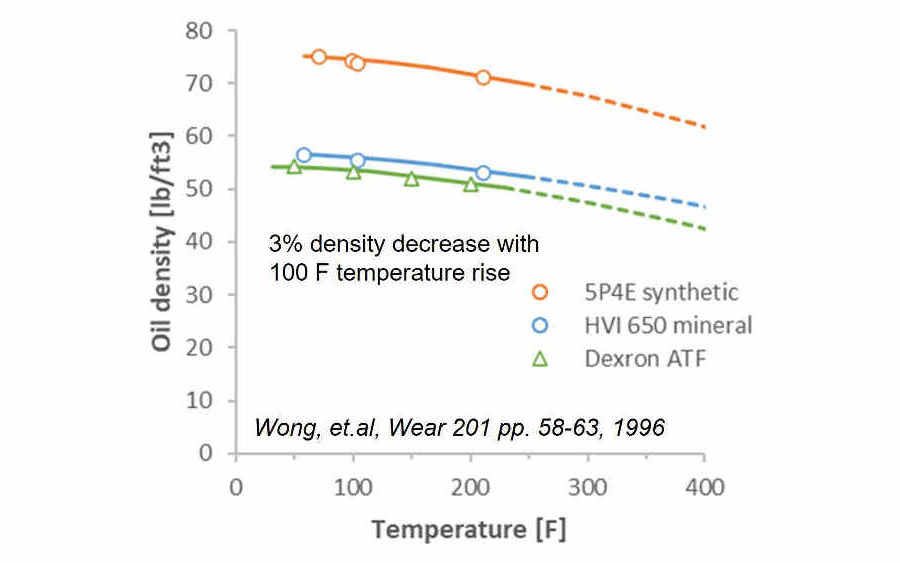
Density decrease with temperature
The Anton Paar lab instrumentation web site provides some sample density measurements of Dexron ATF and Wong et.al. provides additional data measuring both synthetic and mineral based oils.
A 100 F temperature change reduces the density by approximately 3%. The falloff is approximately linear at low temperature, however the density falls off exponentially as temperatures approach the boiling point.
The damping force decrease due to oil density changes is less than the effect of hot oil on the spring stiffness of the shim stack. Shim ReStackor calculations account for both effects when correcting for temperature changes.
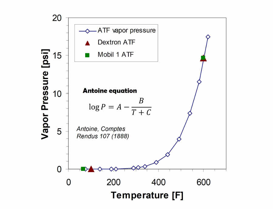
Vapor pressure of hydraulic oil
Cavitation in hydraulic circuits is dictated by the fluid vapor pressure and gasses dissolved in the suspension oil. The material safety data sheets available for Mobil 1 ATF gives the vapor pressure at the normal boiling point and at atmospheric conditions. Chevron provides similar data for Dextron automatic transmission fluid.
The combined data provides an estimate of suspension oil vapor pressure. At the normal boiling point of water (212 F) the vapor pressure of ATF is less than 0.1 psi. At temperatures around 600 F the vapor pressure approaches atmospheric pressure.
By design, the vapor pressure of suspension oils is extremely low. As long as the shock oil is below the boiling point of water (212 F) the typical assumption of zero vapor pressure is reasonable for evaluating cavitation limits. Dissolved gas in the suspension oil is by far the bigger issue in evaluating cavitation limits.
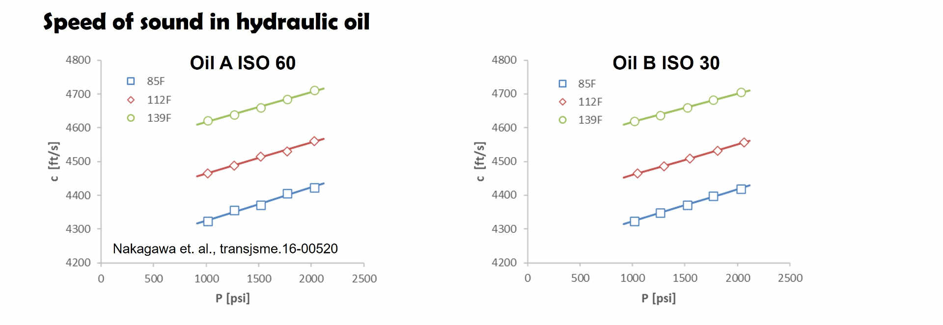
Speed of sound in hydraulic oil
Nakagawa measured the speed of sound in hydraulic oil. Oil B is similar to ATF, Oil A is a more viscous version. The data shows the speed of sound is approximately 4600 ft/sec at a shock oil temperature of 139 F.
The typical shock body length is approximately five inches. At 4600 ft/sec it takes 0.09 milliseconds for a pressure signal to transfer from the main piston to the compression adjuster.
The 0.09 millisecond signal transfer time allows the shock to respond to pressure signals at 5500 Hz. The example confirms common expectations. The transfer of pressure signals through shock absorber circuits is virtually instantaneous.
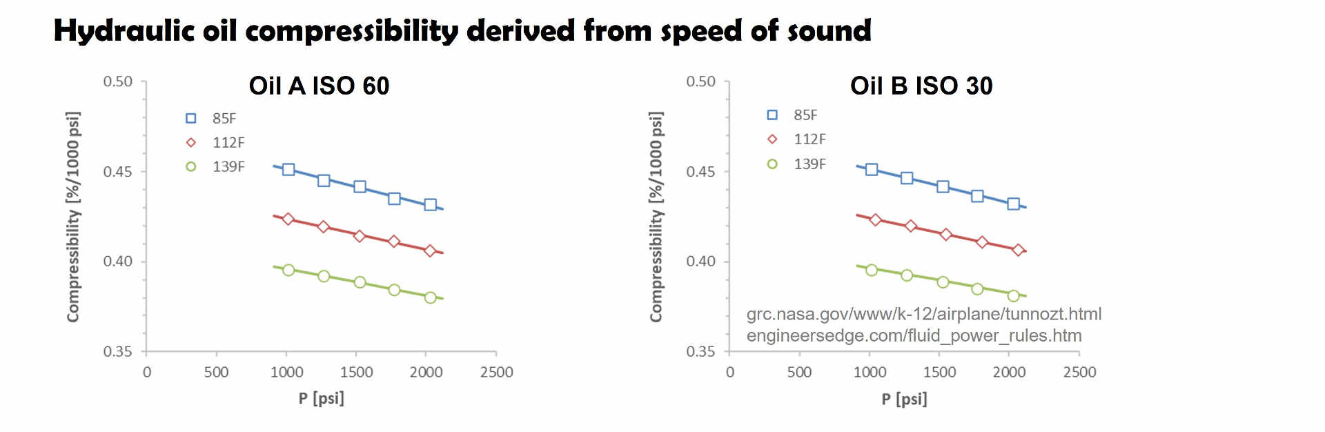
Oil compressibility
The speed of sound is a measure of the speed of density waves propagation through the fluid. NASA shows the speed of sound is directly related to the fluid compressibility. Thus, the Nakagawa speed of sound measurements also provide a direct measure of oil compressibility.
At a shock temperature of 139F a 1,000 psi increase in fluid pressure compresses the oil by 0.4%. Engineers edge publishes a similar design rule of 0.5% compression at 1,000 psi for design of hydraulic systems.
Shim ReStackor suspension response calculations show a 3.7 foot freefall bottoms a stock ’14 yzf450 rear shock. The jump landing ground impact produces a peak pressure drop of 315 psi across the main piston.
Given an oil compressibility of 0.4% at 1,000 psi the 315 psi shock pressure produces a 0.4*(315/1000)= 0.13% increase in oil density. The oil compressibility allows the five inch shock stroke to jump forward 0.006 inches in a process know as surge in hydraulic systems.
The damping force of shock absorbers scales directly with oil density. A 0.13% increase in oil density produces a 0.13% increase in damping force.
The shock absorber bump energy absorbed is equal to the force times distance work done through the stroke. The oil density increase creates a 0.13% increase in damping force while the hydraulic surge from oil compressibility shortens the shock stroke by 0.13%. The 0.13% stiffer damping coupled with a 0.13% shorter stroke results in no change in the force times distance work done.
Oil compressibility of 0.4% on a 1,000 psi pressure increase produces little effect on shock absorber performance. More importantly the density increase increases the damping force while hydraulic surge shortens the shock stroke resulting in no net change in absorbed bump energy confirming the commonly reported result: “Shock absorber oil is virtually incompressible”.
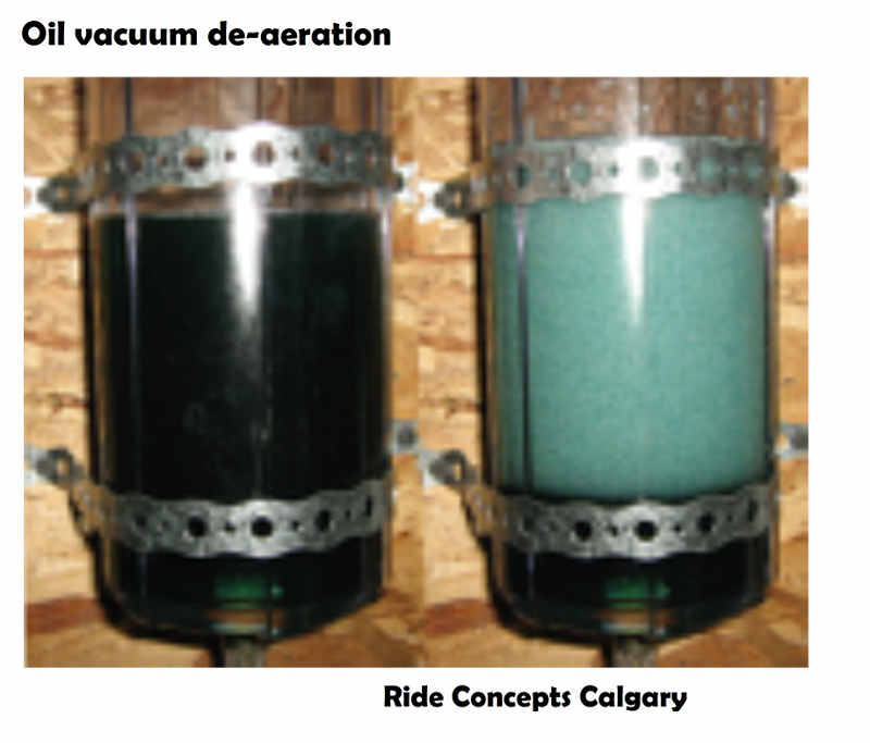
Dissolved gas in suspension oil
A fresh bottle of factory sealed suspension oil contains 10% by volume dissolved gas. Pull a vacuum on the oil and the dissolved gas boils out causing the oil to foam as demonstrated by the Ride Concepts, Calgary photo below.
The Ostwald coefficient defines the dissolved gas as a volume fraction of the liquid. For nitrogen or air in suspension oils the Ostwald coefficient is approximately 10%.
While the Ostwald coefficient remains constant the mass of dissolved gas changes with temperature and pressure. At an atmospheric pressure of 14.7 psi the oil contains 10% by volume dissolved air. Pressurizing the shock bladder to 147 psi compresses the dissolved gas 10:1 resulting in a dissolved gas volume of 1%. Conversely, increasing temperature expands the dissolved gas forcing gas release until the dissolved gas volume falls within saturation limits. This is why hot shock absorbers are more prone to cavitation.
Over time nitrogen diffuses through the shock bladder or around the sliding seals of a piston reservoir and saturates the shock oil with 10% by volume pressurized gas. Diffusing gas through a shock bladder to saturate the pressurized oil typically requires about four months.
Once the oil is saturated with pressurized gas dropping the shock chamber pressure below the gas reservoir pressure allows the dissolved gas to boil out and foam the oil.
To suppress oil foaming shock absorber compression adjusters and fork base valves are tuned to produce high back pressure and keep the shock chambers pressurized at or above the gas reservoir pressure.
Dissolved gas in suspension oils make the oil behave like a hot bottle of coca-cola. Keep the oil under pressure and the fluid behaves like a liquid. When the pressure drops below the dissolved gas pressure the gas boils out and foams the oil.
Shim ReStackor calculations compute the pressure in each chamber of the shock. A central use of Shim ReStackor is tuning compression adjusters and fork base valves to keep each chamber of the shock pressurized above the dissolved gas pressure. (linky, sec 3h1).
Shim ReStackor oil properties
The shock operating temperature, oil kinematic viscosity at two temperatures and oil density at the input reference temperature specify the oil properties needed for Shim ReStackor calculations.
The Andrade equation is used to correct viscosity for temperature changes, the Antoine equation to correct vapor pressure, Ostwald coefficients to account for dissolved gas with additional corrections for temperature effects on oil density and shim stiffness.
Physics based pressure and temperature corrections for oil properties allow Shim ReStackor calculations to accurately scale fluid dynamic pressure losses across the entire range of shock absorber operation.